OrbitalHub

Where curiosity reaches escape velocity.

Domain is for sale. $50,000,000.00 USD. Direct any inquiries to contact@orbitalhub.com.

Archive for the Robotic Exploration category

September 14, 2009

PROBA-2

Posted by


Credits: ESA – P. Carril, 2009


PROBA-2 is part of an ESA program called In-Orbit Technology Demonstration Program, which is dedicated to the demonstration of innovative technologies.


The PROBA-2 payload consists of scientific instruments that will make observations of the Sun in the ultraviolet portion of the spectrum and will measure certain properties of the plasma surrounding the spacecraft.


Among the new equipment and technologies demonstrated by PROBA-2 are new models of star trackers, GPS receivers, and reaction wheels, a new type of lithium-ion battery, an advanced data and power management system, composite carbon-fibre and aluminum structural panels, and magnetometers. PROBA-2 also hosts a digital Sun-sensor, an experimental solar panel, and a xenon gas propulsion system.


PROBA-2 will be launched onboard the same launch vehicle as SMOS. While the SMOS Mission will provide global maps of moisture over the Earth’s landmasses and salinity over the oceans, PROBA-2 is a small technology demonstrator. Launched as a secondary payload, PROBA-2 will orbit in the same plane as SMOS, but at a lower altitude. The planned mission duration is two years.


The spacecraft is a 600 mm x 700 mm x 850 mm box-shaped structure, with a mass of 130 kg. Aluminum honeycomb panels make the primary mechanical structure of the spacecraft. The two deployable solar panels and the one outer solar panel provide a maximum of 110 Watts of electrical power. A lithium-ion battery provides power during eclipse periods. A single 20 mN thruster is used for orbit adjustments.
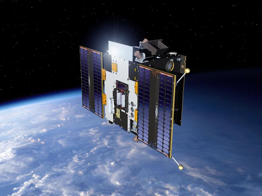
 

Credits: ESA – P. Carril, 2009


PROBA-2 is three-axis stabilized. Attitude changes are performed using four reaction wheels that can be unloaded by magnetorquers, while the attitude determination is provided by star trackers, GPS sensors, and a three-axis magnetometer.


The spacecraft was built by Verhaert Design & Development NV, Belgium.


The scientific payload comprises of four experiments: two for solar observations (LYRA and SWAP) and two for space weather measurements (DSLP and TPMU).


LYRA is a Lyman-Alpha radiometer that will monitor four bands in a very wide ultraviolet spectrum. SWAP (the Sun Watcher using Active Pixel-sensor) will make measurements of the Sun’s corona. DSLP (Dual Segmented Langmuir Probes) will make measurements of the electron density and temperature in the background plasma. TPMU, which is the Thermal Plasma Measurement Unit, will measure ion densities and composition.


Launch services for the PROBA-2 mission are provided by EUROCKOT Launch Services GmbH. PROBA-2 will achieve its lower orbit by an orbit change maneuver of the Breeze-KM upper stage of the Rockot launch vehicle.


Credits: ESA – P. Carril, 2009


Rockot is a three-stage liquid propellant launch vehicle based on the Russian SS-19 Intercontinental Ballistic Missile (ICMB).


Rockot’s first and second stages (provided by SS-19) are completed by a third re-ignitable stage, the Breeze-KM upper stage. Rockot can deliver 1950 kg payloads to Low Earth Orbits (LEOs).


The length of the launch vehicle is 29 m. The external diameter of the stages is 2.5 m, while the payload fairing has an external diameter of 2.6 m and a height of 6.7 m. The mass of the vehicle at launch is 107 metric tons.


PROBA-2 will be carried into orbit from Plesetsk Cosmodrome, Russia. The operational orbit is a 700 km sun-synchronous orbit, with a 98 degree inclination.


You can read more about PROBA-2 on ESA’s dedicated web site. ESA’s web site also provides information about PROBA-1, which is already flying, and future PROBA missions, like PROBA-3 and PROBA-V.
 

August 29, 2009

ISRO Lost Contact With Chandrayaan-1

Posted by


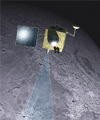
Credits: ISRO


After nine months of operation, Chandrayaan-1 failed to communicate with the base. The Indian Space Research Organization (ISRO) abruptly lost contact with the spacecraft on Saturday, September 29, 2009.


If this is the end of Chandrayaan-1, the mission covered only nine months of its scheduled two-year operational life. I really hope that this is a minor obstacle that the ISRO will be able to overcome. ISRO stated that the Chandrayaan-1 mission was able to meet most of its scientific objectives.


The Chandrayaan-1 scientific payload contains a diverse collection of instruments. The instruments were designed and developed by ISRO, ESA, NASA, and the Bulgarian Space Agency.


There are two instruments that are used to map the surface of the Moon: the Terrain Mapping Camera (TMC) and the Lunar Laser Ranging Instrument (LLRI). The X-ray spectrometer onboard the spacecraft measures the concentration of certain elements on the lunar surface and monitors the solar flux in order to normalize the results of the measurements taken. The mineralogical configuration of the surface is mapped by four instruments: the Hyper Spectral Imager (HySI), the Sub-keV Atom Reflecting Analyzer (SARA), the Moon Mineralogy Mapper (M3), and the Near-Infrared Spectrometer (SIR-2). The Radiation Dose Monitor (RADOM-7) records the radiation levels in the lunar orbit.


You can find out more about Chandrayaan-1 on the ISRO’s dedicated web page.


July 10, 2009

End of Journey for Ulysses

Posted by


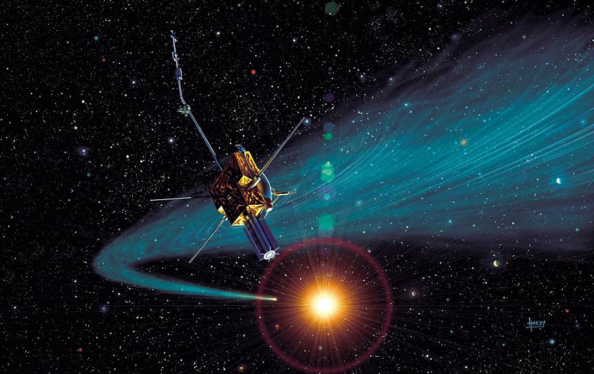
Credits: ESA – D. Hardy


On June 30, 2009, the Ulysses mission came to an end, one year after the predicted mission end date. Ulysses is one of the longest space missions to date, and holds the record for the longest running ESA operated spacecraft, with a total mission duration of 6,842 days (18 years, 8 months, and 24 days).


A joint venture of NASA and ESA, Ulysses was launched on October 6, 1990, from the STS-41 Space Shuttle Discovery mission. Being an Out-Of-The-Ecliptic (OOE) mission, the Ulysses mission studied the Sun at all latitudes. The initial gravity assist at Jupiter on February 8, 1992, injected the spacecraft in an orbit around the Sun with an inclination to the ecliptic of 80.2 degrees.


Besides studying the north and south poles of the Sun, Ulysses also made observations on Jupiter and the comets Hyakutake and McNaught-Hartley.


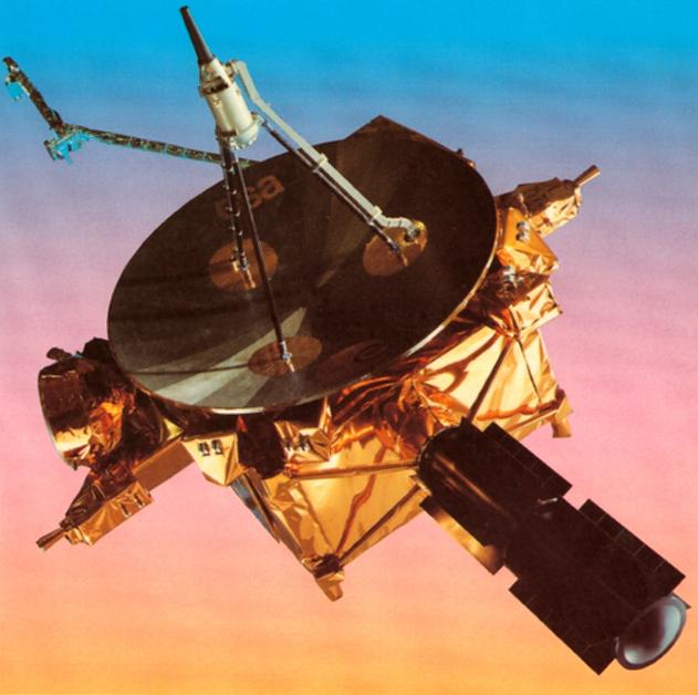
The spacecraft is box-shaped, 3.2×3.3×2.1 m in size. Three external features of the spacecraft are the High Gain Antenna (HGA), which is a 1.65 m diameter parabolic dish, the Radio-isotope Thermoelectric Generator (RTG), and the two 35 m antennae for the Unified Radio and Plasma (URAP) instrument. The HGA was used for communicating with ground-based stations in both X-band and S-band radio frequency bands.


Credits: ESA


If you are passionate about spacecraft design, an overview of the Ulysses spacecraft, with subsystem schematics and descriptions of all units, is available.


The link contains presentations of the Attitude and Orbit Control Subsystem, the Telemetry, Tracking, and Command Subsystem, the Data Handling Subsystem, and the Power and Thermal Subsystem. It is 1980s technology, but very tasty food for an engineer’s brains.


During its long-duration mission, Ulysses made observations above and below the poles of the Sun. Fundamental scientific discoveries and contributions to our understanding of the Sun and the heliosphere were made. Due to the characteristics of its orbit, Ulysses was able to perform direct measurements of interstellar dust and gas.


You can find out more about Ulysses on ESA’s and NASA’s websites.


Planetary Radio released an interview with Nigel Angold, the ESA Ulysses Mission Operations Manager. Find out how engineers kept the Ulysses spacecraft alive for so long. I invite everyone to listen to it.


February 17, 2009

Dawn and the Flyby of Mars

Posted by


Credits: NASA/JPL


The Dawn spacecraft is currently performing the Mars flyby phase of its mission. The purpose of the Mars flyby is to alter the trajectory of the spacecraft in order to rendezvous with its first scientific target in the main asteroid belt.


The spacecraft will come within 549 km of the surface of Mars on February 17, 2009, at 4:28 PST.


The flyby is a gravity assist maneuver used in orbital mechanics to alter the trajectory of a spacecraft. The gravity assist is also known as a gravitational slingshot. The first ever gravity assist maneuver was performed by Mariner 10 in February 1974, and most of the interplanetary missions have made use of it since then.


The scientific objective of the Dawn mission is to answer important questions about the origin and the evolution of our solar system. The currently accepted theory about the formation of our solar system states that Jupiter’s gravity interfered with the accretion process, thereby preventing a planet from forming in the region between Jupiter and Mars. This led to the formation of the asteroid belt.


The asteroids chosen as scientific targets for the Dawn mission are Vesta and Ceres. Due to their size, they have survived the collisional phase, and it is believed that they have preserved the physical and chemical conditions of the early solar system. The asteroids have followed different evolutionary paths and have dissimilar characteristics, which makes them perfect research subjects.


Credits: NASA/JPL


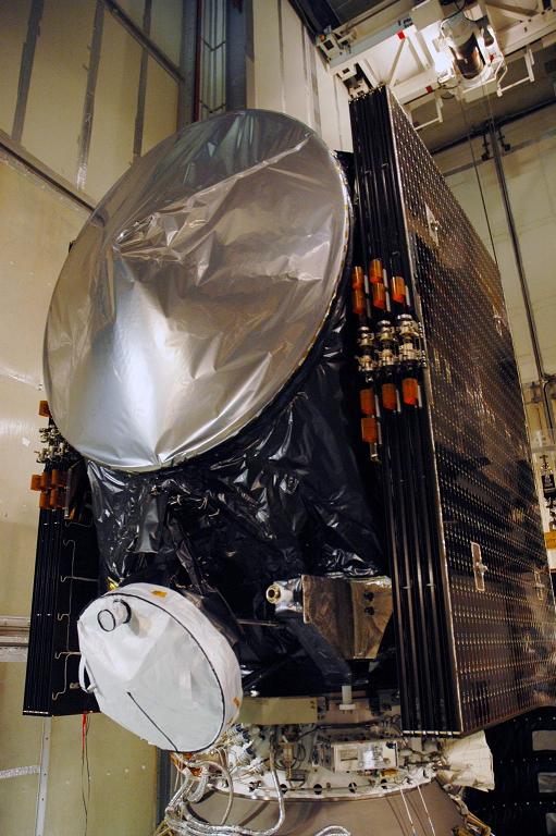
The design of the Dawn spacecraft is based on Orbital’s STAR-2 series, and uses flight-proven components from other Orbital and JPL spacecraft: the propulsion system is based on the design used on Deep Space 1, the attitude control system used on Orbview, a hydrazine-based reaction control system used on the Indostar spacecraft, and command and data handling, as well as flight software, from the Orbview program.


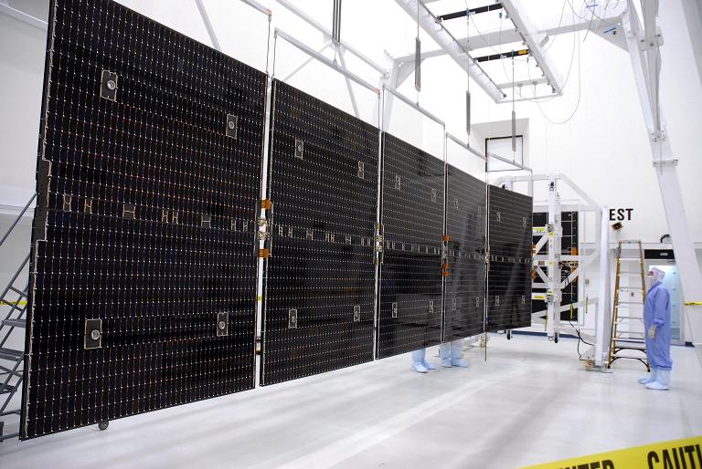
The core structure of the spacecraft is a graphite composite cylinder, while the panels are aluminum core with aluminum/composite face sheets.


The central cylinder hosts the hydrazine and xenon tanks. The hydrazine tank can store 45 kg of fuel, while the xenon tank has a capacity of 450 kg.


The attitude control system (ACS) uses star trackers to estimate attitudes in cruise mode. A coarse Sun sensor (CSS) allows ACS to keep the solar panels normal to the Sun-spacecraft line. ACS also uses the hydrazine-based reaction control system for the control of attitude and for desaturation of the reaction wheels.


Credits: NASA/George Shelton


The solar panels are capable of producing more than 10 kW at 1 AU and 1 kW at 3 AU (on Ceres’ orbit).


The command and data handling system (CDHS) is based on a RAD6000 board running VxWorks. The software is written in C. There are 8GB available on the board as storage for engineering and scientific data.


The scientific payload consists of the Framing Camera (FC), the Gamma Ray and Neutron Detector (GRaND), and the visible and infrared (VIR) mapping spectrometer.


The FC will be used for determining the bulk density, the gravity field, for obtaining images of the surface, and for compiling topographic maps of Vesta and Ceres. In addition, the FC will capture images for optical navigation in the proximity of the asteroids. For reliability purposes, the payload includes two identical cameras that can run independently.


GRaND will serve for the determination of the elemental composition of the asteroids. GRaND is the result of the expertise accumulated during the Lunar Prospector and Mars Odyssey programs.


Credits: NASA/Jack Pfaller


VIR will help map the surface mineralogy of the asteroids. The instrument is a modified version of the visible and infrared spectrometer flying on the Rosetta mission.


The Dawn spacecraft uses ion propulsion to make its journey to Vesta and Ceres. Ion propulsion will also be used by Dawn during the low altitude flights over the asteroids.


While the fact that Dawn’s engines have a thrust of only 90 mN can hardly impress a reader, the important detail to mention when discussing propulsion systems is the specific impulse. Dawn’s engines have a specific impulse of 3100 s. For a chemical rocket, the specific impulse ranges from 250 s for solid rockets to 450 s for bipropellant liquid rockets. The only drawback (if this can be regarded as a drawback) is that the ion engines must be fired for much longer in order to achieve an equivalent trajectory.


With such high specific impulse engines, Dawn makes use of the fuel onboard in a very efficient way. The fuel used is xenon, a heavy noble gas placed in group 8A of the periodic table. The power produced by the large solar panels is used to ionize the fuel and then accelerate it with an electric field between two grids. In order to maintain a neutral plasma, electrons are injected into the beam after acceleration.


Credits: NASA/Amanda Diller


Dawn was launched from Cape Canaveral Air Force Station and injected on an interplanetary trajectory by a Delta II launch vehicle.


The main contributors to the Dawn mission are the University of California in Los Angeles (science lead, science operations, data products, archiving, and analysis), the Jet Propulsion Laboratory (project management, systems engineering, mission assurance, payload, navigation, mission operations, level zero data), and the Orbital Sciences Corporation (spacecraft design and fabrication, quality assurance, and payload integration).


The scientific payload was provided by the Los Alamos National Laboratory, the German Aerospace Center, the Max Planck Institute, and the Italian Aerospace Center. The Deep Space Network is responsible for data return from the spacecraft.


For more information about Dawn, you can visit the Dawn Mission Home Page on the JPL web site.


January 4, 2009

The JPL Twins Are Five Years Old

Posted by


Credits: NASA


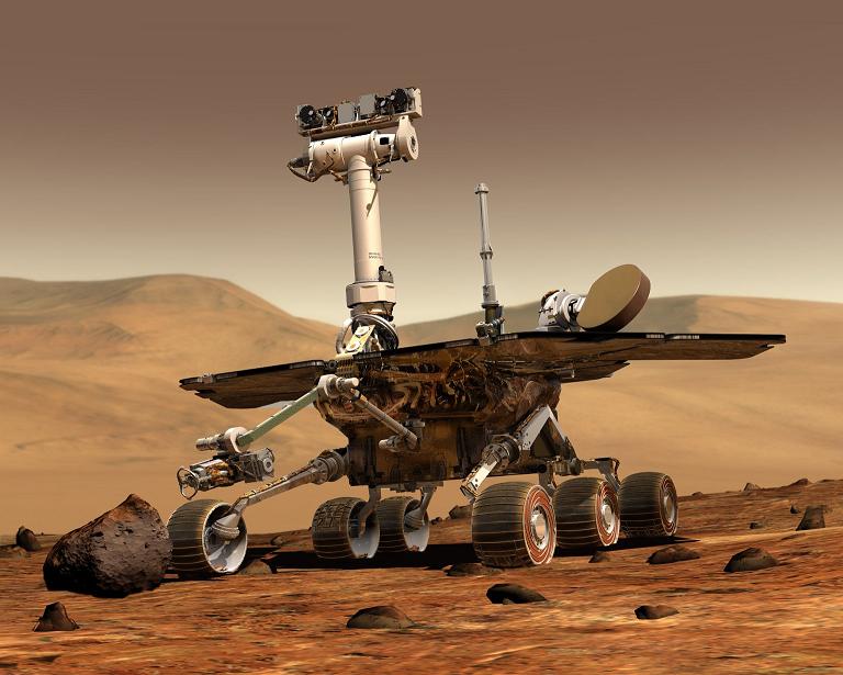
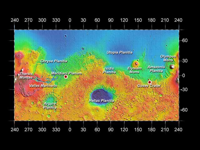
On January 3, 2004, the MER-A rover a.k.a. Spirit landed on Mars at the Gusev Crater. The second rover, MER-B a.k.a. Opportunity, followed twenty-one days later and landed at the Meridiani Planum.


They were both designed to operate for three months on the surface of Mars. Five years later, they are still operational and NASA has planned new missions for them.


Considering the harsh conditions on Mars, NASA’s twin rovers have accomplished remarkable things: they have returned a quarter-million images, driven more than thirteen miles, climbed a mountain, descended into impact craters, and survived dust storms. Using the Mars Odyssey orbiter as a communication relay, the rovers have sent more than 36 GB of scientific data back to Earth.


“These rovers are incredibly resilient considering the extreme environment the hardware experiences every day,” said John Callas, JPL project manager for Spirit and Opportunity. “We realize that a major rover component on either vehicle could fail at any time and end a mission with no advance notice, but on the other hand, we could accomplish the equivalent duration of four more prime missions on each rover in the year ahead.”


Credits: NASA


Digging into the MER mission archive, one detail caught my eye. The rovers carry plaques commemorating the crews of Columbia and Challenger, and some of the landmarks surrounding the landing sites of the rovers are dedicated to the astronauts of Apollo 1, Columbia, and Challenger.


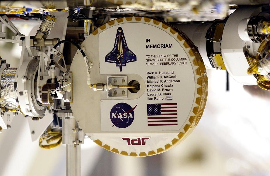
Spirit is carrying a plaque commemorating the STS-107 Space Shuttle Columbia crew, which has been mounted on the high-gain antenna of the rover.


The names of the STS-107 crew are inscribed on the plaque: Rick D. Husband, William C. McCool, Michael P. Anderson, Kalpana Chawla, David M. Brown, Laurel B. Clark, and Ilan Ramon. Their names are now looking over the Martian landscapes.


To further honor their memory, the landing site of the MER Spirit is called the Columbia Memorial Station.


Credits: NASA


Three of the hills surrounding the Columbia Memorial Station are dedicated to the Apollo 1 crew: Gus Grissom, Ed White, and Roger Chafee. Grissom Hill is located 7.5 km to the southwest of Columbia Memorial Station, White Hill is 11.2 km northwest of the landing site, and Chafee Hill is located 14.3 km south-southwest of the landing site.


The area where Opportunity landed in the Meridiani Planum is called Challenger Memorial Station, in memory of the last crew of the Space Shuttle Challenger: Francis R. Scobee, Michael J. Smith, Judith A. Resnik, Ellison S. Onizuka, Ronald E. McNair, Gregory B. Jarvis, and Sharon Christa McAuliffe. I remember that Sharon Christa McAuliffe was NASA’s first teacher in space.


“The journeys have been motivated by science, but have led to something else important,” said Steve Squyres of Cornell University, in Ithaca, N.Y. Squyres is principal investigator for the rover science instruments. “This has turned into humanity’s first overland expedition on another planet. When people look back on this period of Mars exploration decades from now, Spirit and Opportunity may be considered most significant not for the science they accomplished, but for the first time we truly went exploring across the surface of Mars.”


December 15, 2008

MRO Completed First Phase of Its Mission

Posted by


Credits: NASA/JPL

The Mars Reconnaissance Orbiter (MRO) has completed the first phase of its science mission. During this phase, the orbiter returned seventy-three terabits of science data to Earth, which is more than all earlier Mars missions combined. The next phase of the MRO mission will take two years.


The list of scientific discoveries and observations made by MRO is stunning. We know now that Mars has a long history of climate change and that water was present in liquid form on its surface for hundreds of millions of years.


Signatures of a variety of watery environments have been observed, so future missions will be aware of locations that might reveal evidence of past life on Mars, if it ever existed.


MRO has imaged nearly forty percent of the Martian surface at such a high resolution that house-sized objects can be seen in detail. MRO has also conducted a mineral survey of the planet, covering sixty percent of its surface. Global weather maps were assembled using the data returned by MRO, and profiles of the subsurface and the polar caps have been put together using the radar mounted on MRO.


Credits: NASA/KSC

“These observations are now at the level of detail necessary to test hypotheses about when and where water has changed Mars and where future missions will be most productive as they search for habitable regions on Mars,” said Richard Zurek, Mars Reconnaissance Orbiter project scientist.


The images returned by MRO have been used by the Phoenix team to change the spacecraft’s landing site, and will help the NASA scientists select landing sites for future missions, like the Mars Science Laboratory (MSL).


Another role played by MRO was to relay commands to and to return data from the Phoenix lander during the five months the lander was operational on the Martian surface. MRO shared this task with the Mars Odyssey Orbiter.


MRO lifted off on August 12, 2005, from launch Complex 41 at Cape Canaveral Air Force Station. The cruise phase of the mission lasted seven months, the spacecraft reaching Mars orbit on March 10, 2006, after traveling on an outbound arc intercept trajectory.


MRO entered the final low orbit suited for science-data collection on November 2006, after slowing down in the Martian atmosphere by using aerobraking for five months. The first phase of the mission consisted in gathering information about Mars, and the remaining time left of its operational life will be dedicated mainly to using the spacecraft as a communication relay.


Credits: NASA/KSC

The declared goals of the MRO mission are: to determine whether life ever arose on Mars, to characterize the climate of Mars, to characterize the geology of Mars, and to prepare for human exploration.


The launcher of choice for the MRO mission was the Atlas V-401 launch vehicle, the smallest of the Atlas V family. This was the first launch of an Atlas V on an interplanetary mission.


The Atlas V-401 is a two-stage launch vehicle that does not use solid rocket boosters. The Atlas V-401 is fifty-seven meters tall and has a total mass at liftoff of 333,000 kg. Out of this, about 305,000 kg is fuel. In order to reach Mars orbit, MRO was accelerated to 11 km per second.


The first stage of the Atlas V, the Common Core Booster, is powered by liquid oxygen and RP-1. For the MRO mission, the first stage used a RD-180 engine. The RD-180 engine has an interesting story. It is a Russian-developed rocket engine, derived from the RD-170 used for the Zenit rockets.


Credits: NASA/JPL/KSC/Lockheed Martin Space Systems

Rights to use the RD-180 engine were acquired by General Dynamics Space Systems Division (later purchased by Lockheed Martin) in the early 1990s. The engine is co-produced by Pratt & Whitney and all production to date has been in Russia. According to Pratt & Whitney, RD-180 delivers a ten percent performance increase over current operational U.S. booster engines.


The stage weighs approximately 305,000 kg at launch and it provides about four million Newton of thrust for four minutes.


The upper stage of the Atlas V is the Centaur Upper Stage Booster. The Centaur is powered by liquid oxygen and liquid hydrogen. In the case of the MRO mission, it provided the remaining energy necessary to send the spacecraft to Mars.


The payload fairing used for the MRO mission was four meters in diameter. The role of the payload fairing was to protect the spacecraft from the weather on the ground as well as from the dynamic pressure during the atmospheric phase of the launch.


Lockheed Martin Commercial Launch Services developed the Atlas V as part of the US Air Force Evolved Expendable Launch Vehicle (EELV) program.


There are six science instruments, three engineering instruments, and two science-facility experiments carried by the MRO. The low orbit on which MRO is operating allowed the observation of the surface, atmosphere, and subsurface of Mars in unprecedented detail.


The science instruments are the HiRISE camera (High Resolution Imaging Science Experiment), the CTX camera (Context Camera), the MARCI camera (Mars Color Imager), the CRISM spectrometer (Compact Reconnaissance Imaging Spectrometer for Mars), the MCS radiometer (Mars Climate Sounder), and the SHARAD radar (SHAllow RADar).


Credits: HiRISE/MRO/LPL/NASA


The HiRISE camera provided the highest-resolution images from orbit to date, while the SHARAD can probe the subsurface using radar waves in the 15-25 MHz frequency band (these waves can penetrate the Martian crust up to one kilometer).


The engineering instruments assist the spacecraft navigation and communication. The Electra UHF Communications and Navigation Package is used as a communication relay between the Earth and landed crafts on Mars. The Optical Navigation Camera serves as a high-precision camera to guide incoming spacecrafts as they approach Mars. The Ka-band Telecommunications Experiment Package demonstrated the use of the Ka-band for power effective communications.


The science facility experiments are the Gravity Field Investigation Package, used for mapping the gravity field of Mars, and the Atmospheric Structure Investigation Accelerometers, which helped scientists understand the structure of the Martian atmosphere.


For more details on the MRO scientific payload, you can check out the dedicated page on the MRO mission web site.


The MRO was built by Lockheed Martin for NASA’s Jet Propulsion Laboratory in California. Fully loaded, the spacecraft had a mass of almost two tons. The spacecraft carried 1,149 kg of propellant for trajectory correction maneuvers and for the burns needed for the Mars capture.


Credits: NASA/JPL


The main bus of the spacecraft presents two massive solar arrays that can generate 2,000 W of power. On top, the high-gain antenna is the main means of communication with both Earth and other spacecrafts. The SHARAD antenna is the long pole behind the bus.


Other visible features are the HiRISE camera, the Electra telecommunications package, and the Context Imager (CTX).


You can visit the home page of the MRO mission on the NASA web site.