OrbitalHub

Where curiosity reaches escape velocity.

Domain is for sale. $50,000,000.00 USD. Direct any inquiries to contact@orbitalhub.com.

November 18, 2008

PHOENIX

Posted by


Credits: NASA


In 2002, an instrument on the Mars Odyssey spacecraft detected hydrogen under the Martian surface. This was regarded as clear evidence that there is subsurface water ice on Mars.


In 2003, NASA decided to revive a mission that was cancelled in 2001 due to the fact that a previous mission, the Mars Polar Lander, was lost in 1999. The revived mission was named Phoenix.


A Lander that could reach out and touch the ice was needed. The half-built spacecraft for the previously cancelled mission already had in place a 7.7-foot robotic arm that could do the trick.


A JPL team reviewed the data from the failed mission in 1999 and corrected the mistakes made. Every system used in the previous design was taken apart, tested, and examined. The suspected culprits were the retrorockets used during landing. More than a dozen issues that could have caused a failure of the new planned mission were found and fixed.
 

Credits: NASA / JPL


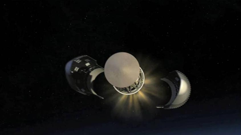
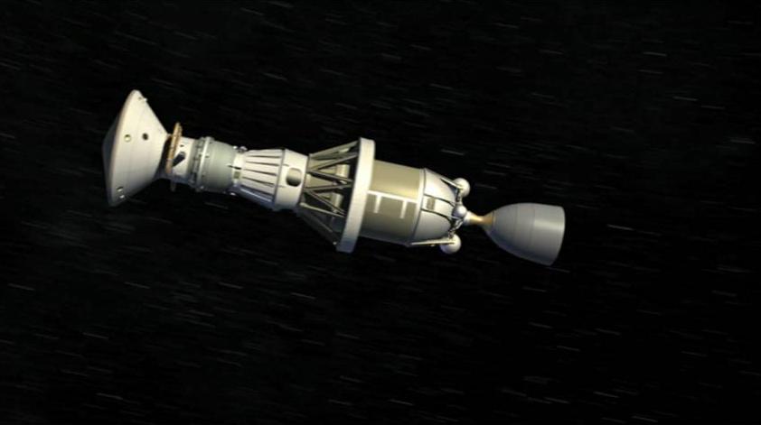
The Phoenix mission inherited a capable spacecraft partially built for the Mars Surveyor Program 2001. As we mentioned, the lessons learned from the Mars Polar Lander helped improve the existing systems. As for any other space mission, the conditions in which the spacecraft operates dictate the design.


In the case of the Phoenix mission, the following phases were considered: the launch, the cruise, the atmospheric entry, the touchdown, and the surface operations phase. The launch induces tremendous load forces and vibrations. The 10-month cruise to Mars exposes the spacecraft to the vacuum of space, solar radiation, and possible impacts with micrometeorites. During the atmospheric entry, the spacecraft is heated to thousands of degrees due to aero braking, and has to withstand tremendous deceleration during the parachute deployment. The extremely cold temperatures of the Martian arctic and the dust storms must be considered during the surface operations phase.
 

Credits: NASA / JPL


Several instruments are mounted on the Lander: the robotic arm (RA), the robotic arm camera (RAC), the thermal and evolved gas analyzer (TEGA), the Mars descent imager (MARDI), the meteorological station (MET), the surface stereo imager (SSI), and the microscopy, electrochemistry, and conductivity analyzer (MECA).


The RA was built by the Jet Propulsion Laboratory and was designed to perform the scouting operations on Mars, such as digging trenches and scooping the soil and water ice samples. RA delivered the samples to the TEGA and the MECA. RA is 2.35 meters long, it has an elbow joint in the middle, and it is capable of digging trenches 0.5 meters deep in the Martian soil.


The University of Arizona and the Max Planck Institute in Germany built the RAC. The camera is attached to the RA, just above the scoop placed at the end of the arm. RAC provided close-up, full-color images.


Credits: NASA / JPL


TEGA was developed by the University of Arizona and University of Texas, Dallas. TEGA used eight tiny ovens to analyze eight unique ice and soil samples. By employing a process called scanning calorimetry, and by using a mass spectrometer to analyze the gas obtained in the furnaces as the temperature raised to 1000 degrees Celsius, TEGA determined the ratio of various isotopes of hydrogen, oxygen, carbon, and nitrogen.


MARDI was built by Malin Space Science Systems. From what I could gather, the MARDI was not used by the Lander due to some integration issues.


The Canadian Space Agency (YAY Canada!) was responsible for the overall development of the meteorological station (MET). Two companies from Ontario, MD Robotics and Optech Inc., provided the instruments for the station.


The SSI served as the eyes of the Phoenix mission. SSI provided high-resolution, stereo, panoramic images of the Martian arctic. An extended mast holds the SSI, so the images were recorded from two meters above the ground.


Credits: NASA / JPL


MECA was built by the Jet Propulsion Laboratory. The instrument was used to characterize the soil by dissolving small amounts of soil in water. MECA determined the pH, the mineral composition, as well as the concentration of dissolved oxygen and carbon dioxide in the soil samples that were collected.


We would like to highlight some of the important moments during the mission:


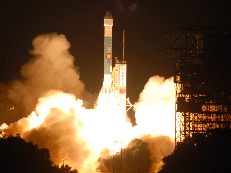
August 4, 2007 – Delta II rocket launch from Cape Canaveral. The three-stage Delta II rocket with nine solid rocket boosters lifted off from Cape Canaveral, carrying the Phoenix spacecraft on the first leg of its journey to Mars.
 

Credits: NASA / JPL -Caltech / University of Arizona


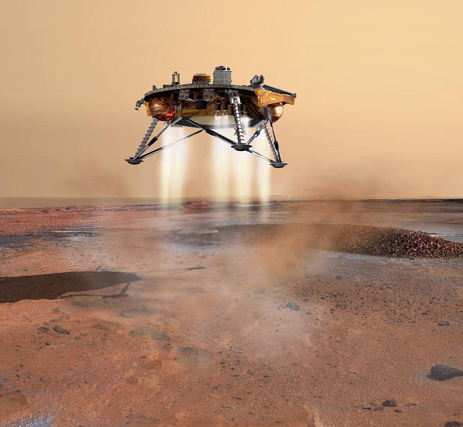
May 25, 2008 – Phoenix Mars Lander touchdown. The Phoenix entered the Martian atmosphere at 13,000 mph. It took 7 minutes for the Lander to slow down with the aid of a parachute and to land using its retrorockets. The mission team did not have to wait long before discovering ice because the blasts from the retrorockets had blown away the topsoil during landing and revealed ice patches under the lander.


November 2, 2008 – Last signal received from the Lander. On this date, communication was established for the last time with Phoenix. Due to the latitude of the landing site, not enough sunlight is available and the solar arrays are unable to collect the power necessary to charge the batteries that operate the instruments mounted on the Lander. At the landing site, the weather conditions are worsening.


November 10, 2008 – Mission declared completed. NASA declares that the Mars Phoenix Lander has completed a successful mission on the Red Planet. Phoenix Mars Lander has ceased communications after being operational for more than five months (the designed operational life of the mission was 90 days).


November 13, 2008 – Mission Honored. NASA’s Phoenix Mars Lander was awarded Best of What’s New Grand Award in the aviation and space category by Popular Science magazine.


Credits: NASA / JPL


The Mars Phoenix Lander made significant contributions to the study of the Red Planet. Phoenix verified the presence of water ice under the Martian surface, and it returned thousands of pictures from Mars. Phoenix also found small concentrations of salts that could be nutrients for life, it discovered perchlorate salt, and calcium carbonate, which is a marker of effects of liquid water.


Phoenix provided a mission long weather record, with data on temperature, pressure, humidity, and wind, as well as observations on snow, haze, clouds, frost, and whirlwinds.


Principal Investigator Peter H. Smith of the University of Arizona led the Phoenix mission. The project management was done at NASA’s Jet Propulsion Laboratory and the development at Lockheed Martin Space Systems in Denver. Other contributors were the Canadian Space Agency, the University of Neuchatel (Switzerland), the University of Copenhagen (Denmark), the Max Planck Institute (Germany), and the Finnish Meteorological Institute.


For more information about the Phoenix mission, check out the NASA Phoenix Mars Lander Page.


Credits: ESA – S. Corvaja 2007


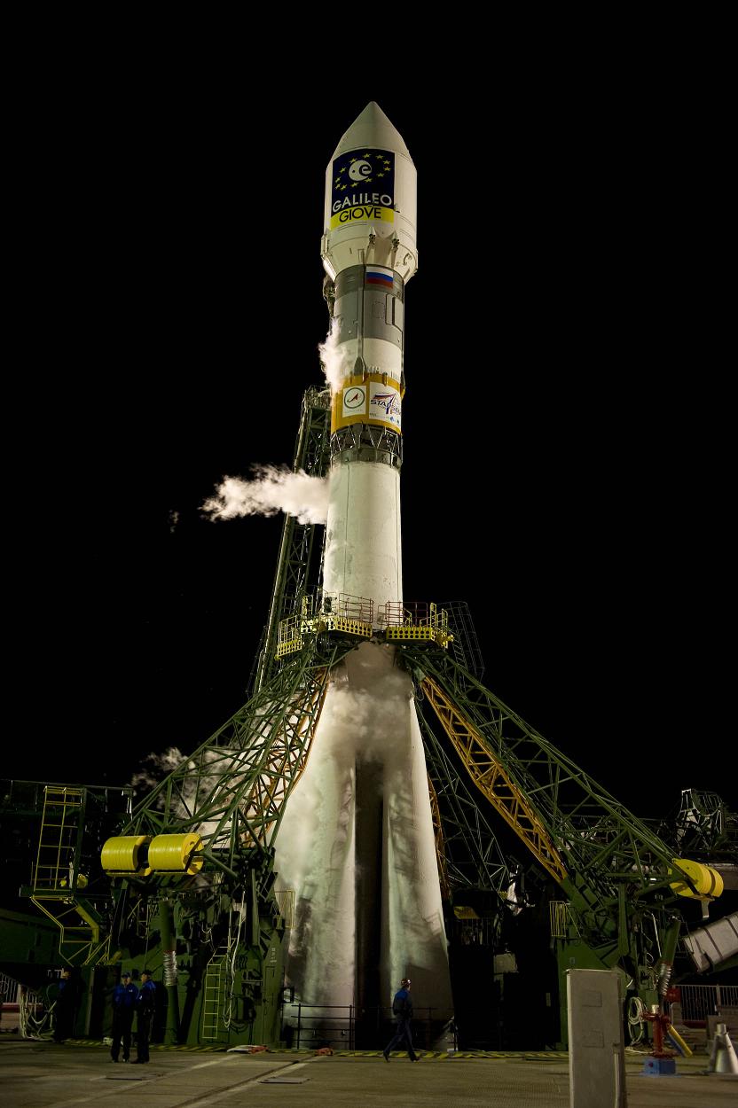
CNES and ESA signed the development contract to build the launch facilities for Soyuz at the Guiana Space Centre on July 19, 2005. The Soyuz launcher will give Europe medium-lift capability and will complete the range of launchers operated by Arianespace, which includes the Ariane 5 heavy-lift launcher and the Vega small launcher.


The Soyuz launchers that will liftoff from Kourou have a number of improvements: an updated digital flight control system, an increased-performance third stage, and the larger Soyuz ST payload fairing.


The launcher has a length of 46.2 meters, a diameter of 10.3 meters, and a liftoff mass of 308 tons. Due to the position of the launch site, close to the equator, the payload capacity of the launcher has increased significantly: 3,150 kg to a geostationary orbit, and 4,900 kg to a sun-synchronous orbit, with a circular altitude of 820 km.


Soyuz is a reliable, four-stage launch vehicle, which has been in production since 1957 and has accounted for more than 1,700 missions to date.


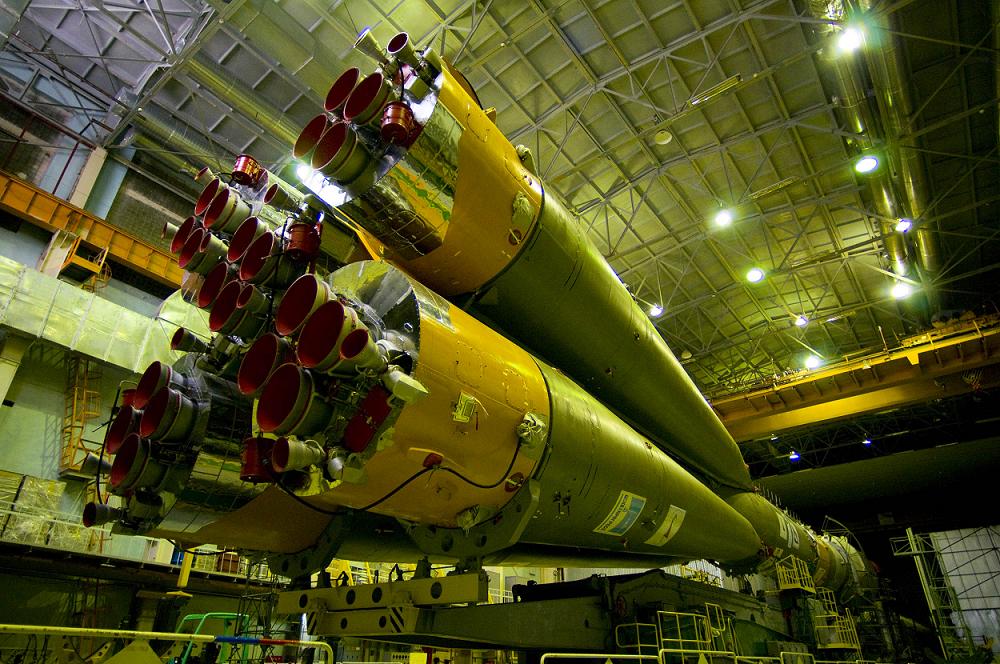
The first stage is composed of the four boosters that are assembled around the central core of the launcher. The RD-107A engines installed on the boosters use liquid oxygen and kerosene as propellant combination. Each engine has four combustion chambers and four nozzles. One aerofin and two movable vernier thrusters per engine are used for the three-axis flight control.


Credits: ESA – S. Corvaja 2008


The second stage consists of the central core surrounded by the boosters. It uses the same propellant combination for powering the RD-108A engine with four combustion chambers and nozzles.


Four vernier thrusters are used for three-axis flight control, after the boosters of the first stage are jettisoned during flight.


The engines of the first two stages are ignited 20 seconds before liftoff. The reason for this is that the launch procedures include monitoring the engine health parameters just before liftoff, while the engines are operating at an intermediate level of thrust. This reminds me of the SpaceX Falcon 1 booster launch procedures. SpaceX engineers perform a similar monitoring procedure for the Merlin engine just before the Falcon 1 liftoff.


The third stage utilizes a RD-0124 engine, also powered by liquid oxygen and kerosene. The liquid oxygen and kerosene tanks are pressurized using helium stored in vessels located in the liquid oxygen tank. The avionics module of the launcher is carried by this stage. The new flight control system improves the accuracy and the control capability for the launcher, as additional flight control authority is needed for the enlarged payload fairing.


Credits: ESA – S. Corvaja 2008


The upper stage of the Soyuz launcher is called Fregat. Fregat is an autonomous and flexible upper stage with its own guidance, navigation, control, tracking, and telemetry systems. It was designed to operate as an orbital vehicle, and it extends the launch capabilities of the Soyuz launcher to medium-Earth orbits, Sun-synchronous orbits, geostationary transfer orbits, and Earth escape trajectories.


The Fregat stage can be restarted up to 20 times in flight, it can provide three-axis stabilization, and perform a spin-up of the spacecraft payload. Fregat uses a bi-propellant propulsion system: UDMH (unsymmetrical dimethylhydrazine) and NTO (nitrogen tetroxide).


The payload fairing is the most visible change to the Soyuz launcher. The new Soyuz fairing has a diameter of 4.11 meters and a length of 11.4 meters. The fairing is based on the configuration used for Ariane 4 vehicles.


The construction of the Soyuz launch base in French Guiana started in early 2007. At the groundbreaking ceremony on February 26, 2007, a number of European space industry officials were present: Jean-Jacques Dordain – ESA Director General, Yannick d’Escatha – President of CNES, Jean-Yves Le Gall – Director General of Arianespace, and Anatoly Perminov – Head of Roscosmos.


In 2007, Arianespace ordered four Soyuz launchers for the early launch missions that are scheduled for the second half of 2009. A contract was also signed in September 2008 for 10 more Soyuz launch vehicles.


The Soyuz launch missions that are scheduled for 2009 signal the beginning of a new chapter in ESA-Russian relations. Stay tuned for more information about the Soyuz launches from French Guiana!


November 7, 2008

Carnival of Space #78

Posted by


Credits: ESA – J. Huart


The Carnival of Space #78 is hosted by Mike Simonsen at SIMOSTRONOMY. OrbitalHub has submitted a post about Vega – the new European small launcher.


Credits: ESA


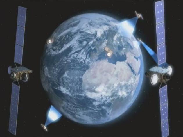
ESA is developing a new satellite communication system that will revolutionize the way Europe gets its information from space. This new communication system is called EDRSS – the European Data Relay Satellite System.


EDRSS will use geostationary satellites to communicate with both ground stations and satellites that are operating in low Earth orbits.


EDRSS will allow low Earth orbit satellites to deliver data continuously, instead of storing it on board and sending it to Earth while flying over a ground station. EDRSS will consist of a network of satellites that will communicate between themselves as well as with the ground stations. This new infrastructure will increase the speed at which ground stations receive data from satellites, thereby improving global communication, navigation, and Earth observation.


EDRSS will serve as a communication infrastructure and it will improve many key services: monitoring earthquakes, forest fires, floods, and aircraft navigation, just to name a few.


You can watch an ESA video cast for more details.


November 4, 2008

SpaceX Enters The Dragon

Posted by


Credits: SpaceX


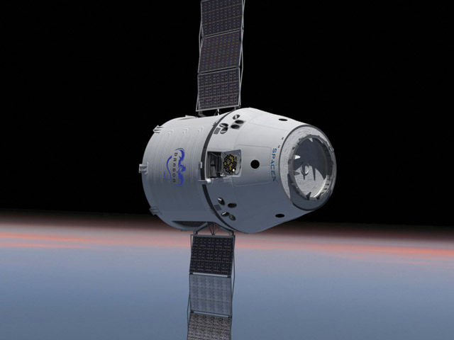
SpaceX just announced the DragonLab Spacecraft. DragonLab is a reusable spacecraft capable of delivering pressurized and un-pressurized payloads to and from space. SpaceX will use Falcon 9 (the heavier version of Falcon 1) to launch the DragonLab spacecraft into orbit.


Dragon will perform two missions in 2009. These missions will test the telemetry, orbital maneuvering and thermal control, and a rendezvous simulation with the Falcon 9 upper stage. The first full cargo mission to ISS is scheduled for 2010.


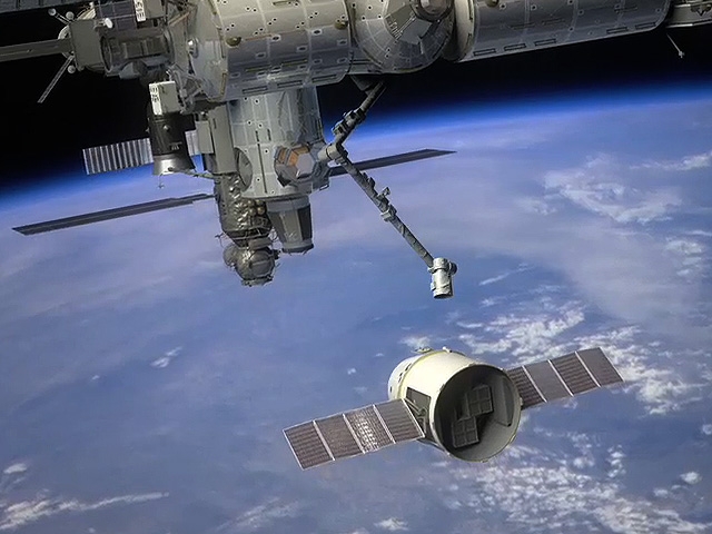
The technical page dedicated to the Dragon spacecraft is quite impressive. Just to mention a few features: down-cargo capability is equal to up-cargo, and up to seven passengers in crew configuration. SpaceX claims fully autonomous rendezvous and docking, but the simulation developed by Odyssey Space Research shows capture operations similar to HTV (the Dragon spacecraft will approach the ISS and then the ISS robotic manipulator will capture the spacecraft and guide it to the docking module).


Credits: NASA/SpaceX


DragonLab will compete with the ATV spacecraft (and the future CTV, LCR versions) that ESA is developing.


SpaceX also announced that it is hosting a workshop on November 6, 2008. Registration is mandatory, so time is of the essence! I am pretty sure the seats are selling like hot cakes…


Credits: ESA – J. Huart


The small-payload market is rapidly expanding. Institutional programs (mostly Earth observation and scientific missions) drive this emerging market. In order to meet the demands of the small-payload market, ESA has transformed the small launcher program initiated by the Italian Space Agency (ASI) in the 1990s into Vega, a co-operative project with other Member States within the ESA framework.


The small-payload market consists of satellites up to 3,000 kg and it stands at around five missions per year. There are many classifications for the satellites in this market, so we will present just one classification for informational purposes. The satellites in this class are divided into three categories: micro-satellites (up to 300 kg), mini-satellites (from 300 kg to 1,000 kg), and small satellites (from 1,000 kg to 3,000 kg).


The orbits required for the deployment of these satellites are mainly Sun Synchronous Orbits (SSO) and Low Earth Orbits (LEO). Vega’s in-orbit launch capability benchmark is 1,500 kg into a 700 km altitude polar orbit. Being designed to cope with a wide range of missions, Vega will address the various market requirements for this class of satellites.


Credits: ESA


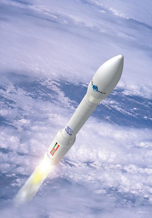
Vega is a single-body launcher composed of four stages. The first three stages are solid propellant stages, while the fourth stage has a liquid propellant engine. Vega is 30 meters high, has a maximum diameter of three meters and a total of 137 tons at lift-off.


There are three main sections: the Lower Composite, the Restartable Upper Module and the Payload Composite.


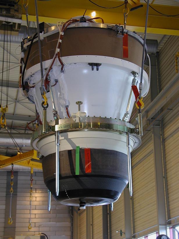
The Lower Composite section consists of the first three stages (the solid propellant stages). The first stage is equipped with a P80-FW motor containing 88 tons of propellant. The second stage contains a Zefiro 23 motor with 23 tons of propellant. The third stage consists of a Zefiro 9 motor with 10 tons of propellant and the stage-interfacing structures.


The technology for the three solid-propellant stages (P80, Z23, Z9) is derived from the Zefiro 16 rocket motor. These motors benefit from the experience acquired by Europe in the field of solid propulsion. Each motor is composed of a thermal-insulated carbon-epoxy monolithic case, the solid propellant HTPB 1912, a nozzle, a thrust vector control system driven by two electro-actuators that operate the movable nozzle, and a control unit that provides pitch and yaw control during the flight. Each stage also includes an ignition subsystem, a safety subsystem, and the interfaces to the other stages.


Credits: ESA/CNES-SOV


The P80 engine was designed for the Vega small launcher, and it helps validate technologies applicable to a new generation of solid boosters for the Ariane 5 launch vehicle. This new design was driven by the goal of minimizing recurring costs, a significant reduction being made with respect to the current metal case boosters.


The Restartable Upper Module is the fourth stage of the launcher. It is also known as the Altitude and Vernier Upper Module (AVUM). The AVUM consists of two modules: the AVUM Propulsion Module and the AVUM Avionics Module.


The propulsion system uses NTO (Nitrogen Tetroxide) and UDMH (Unsymmetrical dimethyl hydrazine) as propellants. The propellants are stored in two identical titanium tanks pressurized by helium. Depending on the mission, the propellant load can be between 250 kg and 500 kg.


The avionics system is largely adapted from existing hardware and/or components already under development (namely subsystems already in use by the Ariane 5 launch vehicle).


The Payload Composite section is composed of the fairing and the payload/launcher interface structure. The fairing is composed of two shells that are jettisoned during flight after the separation of the second stage. The payload/launcher interface is an Adaptor 937, which is a standard interface used on the European launchers. Additional payload adapters can be added for multi-payload missions.


Credits: ESA – J. Huart


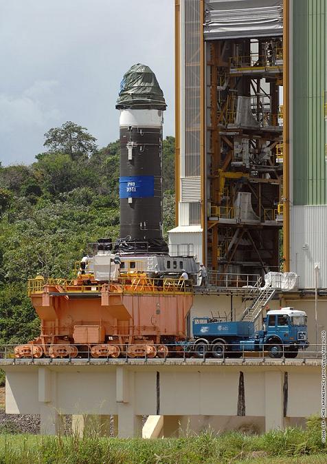
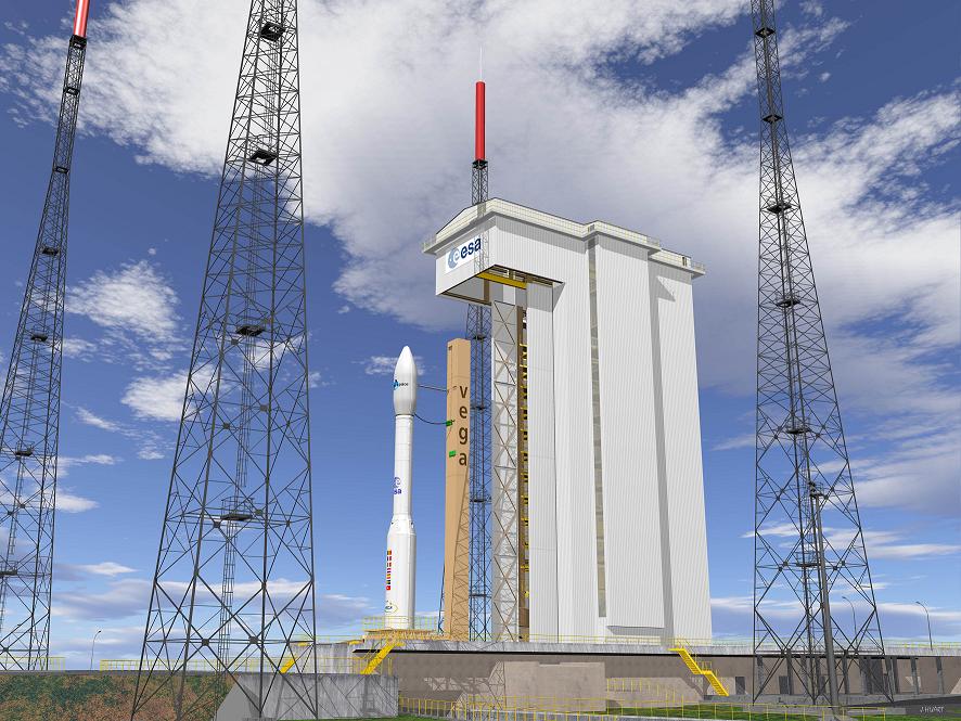
The dedicated Ground Segment for the Vega launcher comprises of the Launch Zone (ZLV – Zone de Lancement Vega) and the Operational Control Center, all located at the European Spaceport at Kourou, in French Guiana. ESA also built a Payload Preparation Complex that will be used for satellite and equipment unpacking, mechanical inspections, the checkout of the payloads, and the final integration of the payload composite before mounting it on top of the launcher.


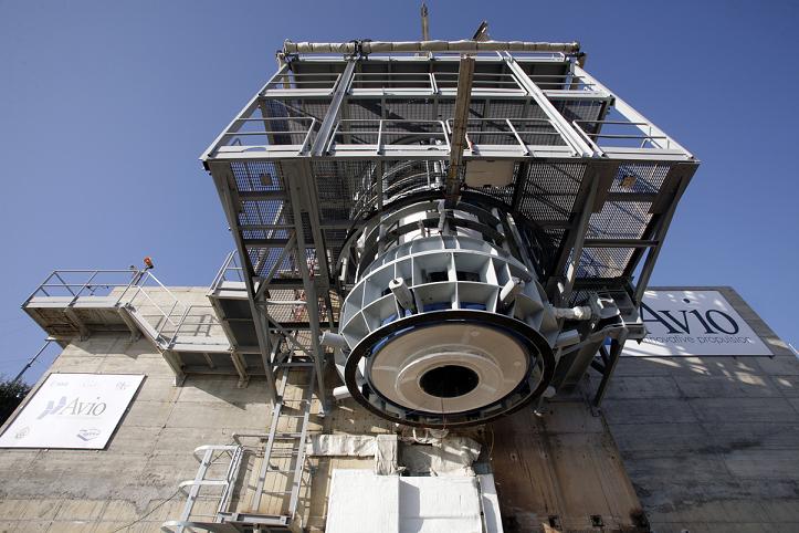
On October 24, 2008, the Zefiro 9 rocket engine passed the first qualification test. There is one additional firing test left for the engine. The Vega launcher’s qualification flight is scheduled to take place by the end of 2009.


Credits: Avio SpA (Italy)


ESA is responsible for the qualification of the launch service and also for sustaining the qualification status during the exploitation phase. Ariane Space will be responsible for Vega’s commercialization and launch operations. The expected launch rate for Vega will be up to four launches per year.


Please stay tuned on the OrbitalHub frequency. We will keep you posted!