OrbitalHub

Where curiosity reaches escape velocity.

Domain is for sale. $50,000,000.00 USD. Direct any inquiries to contact@orbitalhub.com.

Archive for the The Best Of category

October 1, 2008

ESA to Study the Birth of the Universe

Posted by


Some of the most important questions asked in modern science are: how did the Universe begin, how did it evolve to its present state, and how will it continue to evolve in the future? To ask these questions, the remnant radiation that filled the Universe immediately after the Big Bang must be analyzed. This remnant radiation is known as the Cosmic Microwave Background (CMB).
 

Credits: ESA


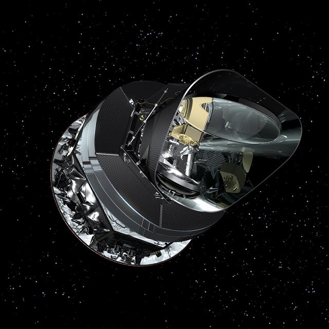
ESA plans to answer these questions with Planck: the first European mission to study the birth of the Universe. The Planck Mission will collect CMB radiation measurements using highly sensitive sensors that are operating at very low temperatures. The measurements will be used to map the smallest variations of the CMB detected to date.


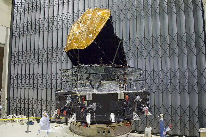
The Planck spacecraft will weigh around 1,900 kg at launch. It is 4.2 m high and has a maximum diameter of 4.2 m. There are two modules that comprise the spacecraft: a service module and the payload module.


The service module contains the systems for power generation, attitude control, data handling and communication, and the warm components of the scientific payload. The payload module contains the telescope, the optical bench, the detectors, and the cooling system (which is of critical importance, as we shall see).


The telescope is an important onboard component. The Planck telescope is a Gregorian telescope with an off-axis parabolic primary mirror 1.75 x 1.5 meters in size. A secondary mirror focuses the incoming microwave radiation on two sets of highly sensitive detectors: the Low Frequency Instrument (LFI) and the High Frequency Instrument (HFI). The Gregorian design offers two key advantages: it is compact and it does not block the optical path.


Credits: ESA/Thales


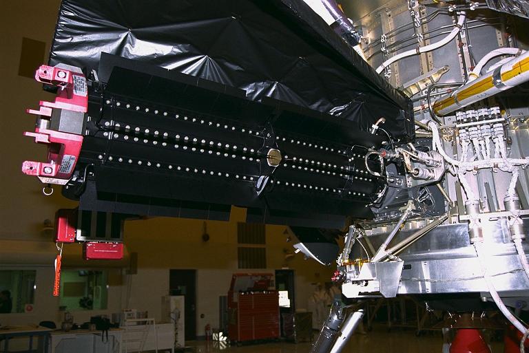
The LFI will be operating at –253 degrees Celsius. The array of twenty-two tuned radio receivers that comprise LFI will produce high-sensitivity, multi-frequency measurements of the microwave sky in the frequency range of 27 GHz to 77 GHz.


The HFI has to be cooled to –272.9 degrees Celsius in order to operate (one tenth of one degree above the absolute zero!). HFI’s fifty-two bolometric detectors will produce high-sensitivity, multi-frequency measurements of the diffuse sky radiation in the frequency range of 84 GHz to 1 THz.


A baffle surrounds the telescope and instruments. The baffle prevents light from the Sun and the Moon from altering the measurements. A complex system of refrigerators is used onboard the spacecraft in order to achieve the temperatures needed for nominal operation. The detectors have to work at temperatures close to the absolute zero, otherwise their own emissions can alter the measurements.


The two instruments will be used to measure the small variations of the CMB across the sky. By combining the measurements, a full sky map of unprecedented precision will be produced. The map will help astronomers decide which theories on the birth and the evolution of the Universe are correct. Questions like ‘what is the age of the Universe?’ or ‘what is the nature of the dark-matter?’ will be answered.


The mission was initially designed as COBRAS/SAMBA (Cosmic Background Radiation Anisotropy Satellite and Satellite for Measurement of Background Anisotropies) because it grew out of two mission proposals that had similar objectives. When the mission was approved in 1996, it was also renamed as Planck in honor of the German scientist Max Planck (1858 – 1947). Max Planck was awarded the Nobel Prize for Physics in 1918.
 

Credits: ESA


The mission is a collaborative effort. The Planck spacecraft was designed and built by a consortium led by Alcatel Alenia Space (Cannes, France). The telescope mirrors are manufactured by EADS Astrium (Friedrichshafen, Germany). The Low Frequency Instrument (LFI) was designed and built by a consortium led by the Instituto di Astrofisica Spaziale e Fisica Cosmica (IASF) in Bologna, Italy. The High Frequency Instrument (HFI) was designed and built by a consortium led by the Institut d’Astrophysique Spatiale (CNRS) in Orsay, France.


The Planck Mission has two predecessors: the Cosmic Background Explorer (COBE) and the Wilkinson Microwave Anisotropy Probe (WMAP).


Credits: ESA


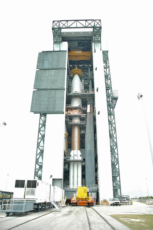
The Planck spacecraft will be launched in early 2009 from Kourou, French Guiana. An Ariane 5 booster will place the spacecraft in a trajectory towards the L2 point. The L2 point stands for Second Lagrangian Point and it is located around 1.5 million kilometers away from Earth in a direction diametrically opposite the Sun. It will be a dual launch configuration, as the Herschel spacecraft will be launched together with Planck.


Between four to six months after the launch, Planck will reach its final position. It will take six more months before Planck will be declared operational.


Planck will perform scientific measurements for fifteen months, allowing two complete sky surveys. The spacecraft will be operational as along as there are resources for the cooling systems onboard.


For more details on the ESA’s Planck Mission you can visit the mission’s home page on the ESA website.
 

September 28, 2008

Power Generation Onboard Spacecrafts (III)

Posted by


In a previous post we presented the most common solution for power generation onboard unmanned spacecrafts (solar cells and secondary batteries) and mentioned some of the manned spacecrafts that employ this solution.


Credits: NASA


However, solar cells, in combination with secondary batteries, are not usable for missions beyond the asteroid belt, because there the sun’s energy becomes too diffuse. As deep space missions were designed, a new power source was required. The radioisotope thermoelectric generators, also known as RTGs, met the requirements for this kind of mission. RTGs are proven, compact, and reliable power sources that can produce up to several kilowatts of power and operate under severe conditions for many years.


RTGs convert the heat generated by a decay of radioactive fuel into electricity. There are two major components that RTGs consist of: the heat source that contains the radioactive material and a set of solid-state thermocouples that convert the heat energy to electricity. The principle that RTGs rely on is not a new discovery. In 1821, Thomas Johann Seebeck discovered the effect that bears his name and that allows us to convert heat directly into electricity using a simple and robust device. An electrical current is generated when two dissimilar electrically conductive materials are connected in a closed circuit and their junctions are kept at different temperatures. The heat generated by the radioactive decay is used to heat the hot junction of the thermocouple, and exposure to the cold outer space is used to maintain the temperature of the cold junction.


Credits: NASA


Over the years, RTGs have been used safely and reliably on many missions. Among these missions: some of the Apollo flights to the moon, the Pioneer spacecrafts, the Viking landers, the Voyager missions, the Galileo mission, the Ulysses mission, and the Cassini-Huygens mission. The present conversion efficiency achieved by the thermocouples is around 10%, and research continues in order to improve it. Because of the internal resistance and other losses, the overall RTG efficiency is typically 6-7%, which means that the amount of waste heat for every unit of electrical energy produced is quite large.


Even if the radioisotopes used present a loss in energy with time, the half-life of the radioisotopes is not a major life-limiting factor of current RTGs. Major life-limiting factors include the degradation of the thermoelectric elements and the breakdown of insulators because of temperature and radiation.


The radiation emissions from RTGs can damage the electronics onboard spacecrafts. This is why it is necessary to mount the units on booms at some distance from the body of the spacecraft or, at least, provide shielding of some sort in the on orbit configuration. One important thing to mention is that in the launch configuration, when the RTG boom cannot be deployed, the radiation exposure cannot exceed the inherent radiation tolerance of the onboard electronics.


There are two more solutions spacecraft engineers employ to generate power onboard spacecrafts and we will present them in our next post. Please come back later to read our conclusion to the series.


September 24, 2008

Scouting the Moon

Posted by


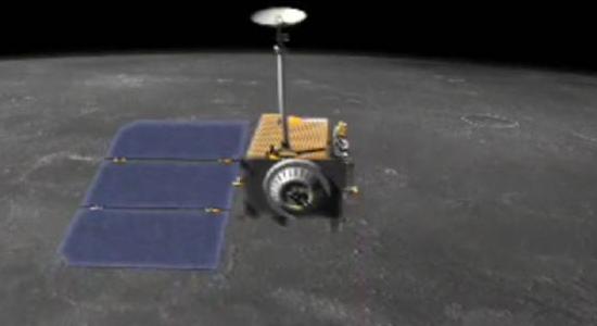
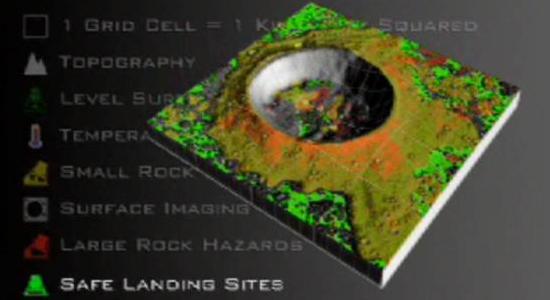
NASA’s return to the Moon requires careful preparation. Finding safe landing sites, locating potential resources, and taking measurements of the radiation environment are some of the tasks the Lunar Reconnaissance Orbiter (LRO) spacecraft will perform while in lunar orbit. LRO is an unmanned mission that will create a comprehensive atlas of the moon’s surface and resources.


The data gathered by LRO will be crucial in designing and building a permanent lunar outpost. The data will also be used to reduce the risk and increase the productivity of the future manned missions to the Moon.


The launch of LRO is scheduled for February 2009. An Atlas V rocket launched from the Kennedy Space Center will place the LRO on a transfer trajectory. After 4 days, the spacecraft will reach the Moon and after performing additional orbital maneuvers, it will move into its final orbit. The LRO’s final orbit will be a circular polar orbit 50 kilometers above the lunar surface.


Credits: NASA


The mission is designed to last for one year, with a possible extension. The total mass of the spacecraft is around 1,000 kilograms, of which 500 to 700 kilograms will be the fuel. The power is supplied by articulated solar arrays, and for the peak and eclipse periods a Li-Ion battery is used. The bandwidth of the communication link will be approximately 100-300 Mbps.


The LRO payload is comprised of six scientific instruments and one technology demonstration.


The Cosmic Ray Telescope for the Effects of Radiation (CRaTER) was built and developed by Boston University and the Massachusetts Institute of Technology in Boston. CRaTER will help explore the lunar radiation environment. The data gathered by measurements will help in the development of protective technologies that will keep future lunar crews safe.


The Diviner Lunar Radiometer Experiment (DLRE) was built and developed by the University of California, Los Angeles and the Jet Propulsion Laboratory in Pasadena, California. DLRE is capable of measuring surface and subsurface temperatures from orbit.


The Lyman-Alpha Mapping Project (LAMP) was built and developed at the Southwest Research Institute in San Antonio. LAMP will be used to map the entire lunar surface in the far ultraviolet spectrum.


Credits: NASA


The Lunar Exploration Neutron Detector (LEND) was developed at the Institute for Space Research in Moscow. This detector will create high-resolution maps of the hydrogen distribution and gather data about the neutron component of the lunar radiation.


The Lunar Orbiter Laser Altimeter (LOLA) was conceived and built at NASA’s Goddard Space Flight Center. LOLA will generate high-resolution three-dimensional maps of the moon’s surface.


The Lunar Reconnaissance Orbiter Camera (LROC), developed at Arizona State University at Tempe, will image the lunar surface in color and ultraviolet. LROC will be able to capture 1 m resolution images of the lunar poles.


The technology demonstration is called Mini-RF Technology Demonstration. The primary goal of this demonstration is to locate subsurface water ice deposits. The advanced single aperture radar (SAR) that will be used is capable of taking high-resolution imagery of the permanently shadowed regions on the lunar surface.


The data gathered by LRO will help us develop a better understanding of the lunar environment. This understanding is essential for a safe human return to the Moon and for the future exploration of our solar system.


September 22, 2008

Power Generation Onboard Spacecrafts (II)

Posted by


After a short introduction to the power systems requirements and design factors, we will continue by covering the first solutions adopted by spacecraft designers: the batteries and the solar arrays (aka solar cells).

Credits: NASA


Batteries were used as a primary source of power onboard early spacecrafts. The obvious limitation is that batteries have limited energy storage capabilities and could not keep spacecrafts operational for more then a few days. Most space missions require a reliable power source running for a longer period of time.


Batteries remain the primary means of energy storage onboard spacecrafts. Batteries are divided into two major categories: primary batteries and secondary batteries.


Primary batteries offer higher energy and power densities but are not rechargeable. They are useful for one-time events such as expendable launch vehicle stages. Secondary batteries are rechargeable batteries.


Solar arrays are very well suited for long missions in space. The life expectancy of a solar cell power system is limited only by the degradation of its components. Spacecrafts operating for extended periods of time become feasible with the development of solar arrays. However, if only solar cells are used for generating power, spacecrafts that enter eclipse periods cannot employ only solar cells for power generation.


Credits: NASA


The first low-powered spacecraft designs were using the spacecraft skin for the solar cell deployment. In the case of drum-shaped spacecrafts, only about 40% of the arrays were illuminated by the Sun at any time. Because most of the time the available area on the fixed spacecraft structure is not enough from the standpoint of power requirements, deployable solar arrays are now used. The solar arrays of this type are deployed from the main structure after the spacecraft is injected into orbit.


The deployable panels are designed as extremely lightweight structures due to the fact that they are firmly locked to the spacecraft during the launch. In order to optimize the generation of power, these panels are designed to allow sun tracking.


Credits: NASA


Considering the limitations of the solar arrays, a reliable solution can be reached by employing solar cells and batteries at the same time. Solar arrays can generate power when direct sunlight is available in orbit, while rechargeable batteries can handle peak loads and provide power during eclipse periods. Solar panels and batteries in combination are a common solution used for the unmanned spacecrafts launched to date. The most notable exception is the deep space mission probes using radioisotope thermoelectric generators (we will cover them in a future post).


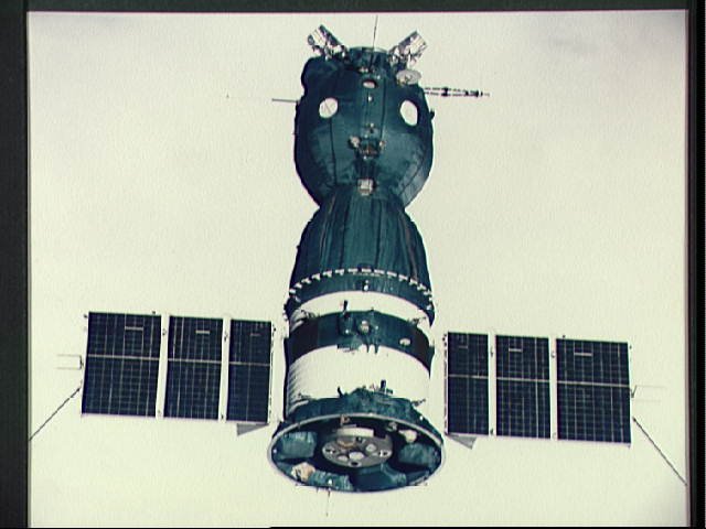
The early manned spacecrafts, including Mercury, some of the Gemini, and the Russian Vostok /Voshkod vehicles, used batteries. The Russian Soyuz employs solar cells and batteries similar to a typical unmanned spacecraft. The space stations built so far, Salyut, Skylab, Mir, and the International Space Station, have all used solar cells as the primary power source, having secondary batteries for load leveling and eclipse periods.


In the following posts we will see what solutions are available for missions that cannot rely on solar power as a primary source of energy.


September 19, 2008

Power Generation Onboard Spacecrafts (I)

Posted by


This post is the first in a series discussing how power is generated onboard spacecrafts.


Credits: NASA


One major component of a spacecraft is the power system. All systems onboard a spacecraft need electricity in order to run. From the early days of space flight, development of this essential system has been a challenge for spacecraft designers.


There are a number of factors that spacecraft designers must take into account: the size, the accessibility, and some operational constraints that can limit the options available. A good example of operational constraints is a spacecraft operating in the Van Allen radiation belts, where radiation exposure can contribute to the rapid degradation of the solar arrays. Other important factors that designers need to consider are the lifetime required by the mission, the orbital parameters, and the attitude control concept employed.


Probably some space geeks (especially science fiction fans) would think of M/AM reactors onboard spacecrafts, but the reality is not as glamorous. Maybe future generations of spacecrafts will use that type of technology, but the present generation is using what some might call primitive technology by comparison.


Credits: NASA


As a general requirement, power systems must control, condition, and process the power received in order to comply with the needs of the systems onboard the spacecraft. The power is received from the primary source, which can be a battery, a solar array, etc. For the duration of the mission, the power system must supply stable and uninterrupted power. If not, the mission is lost.


In the second part of this series, we will take a look at the options available to spacecraft engineers when designing the power system for space missions.


September 15, 2008

Do Spacecrafts Need Annual Checkups?

Posted by


Yes, they do. They really do! One of NASA’s deep space mission probes, New Horizons, is undergoing a check. The mission operators wake the spacecraft out of hibernation once a year. A number of checks are performed: the antennas must be pointed toward Earth, the trajectory must be corrected if needed, and instruments must be calibrated. These checks last more than a usual visit to a doctor… about 50 days. The operators verify the health of the spacecraft, perform maintenance on subsystems and instruments, and gather navigation data.


Credits: NASA


The highlight of the current check was the upload of a new version of the software that runs the spacecraft’s Command and Data Handling system. The brain transplant, as it was called, was a success. The mission team at the Johns Hopkins Applied Physics Laboratory (APL) in Laurel, Maryland, sent the updates through NASA’s Deep Space Network (DSN) to the spacecraft. Two more updates are to be sent for both the Autonomy and Guidance and Control systems.


All commands that are sent to the spacecraft must pass a rigorous development and review process. After the command sequences are tested on the ground, the mission operations team will send them from the New Horizons Mission Operations Center at APL using the DSN, which is operated and managed by NASA’s Jet Propulsion Laboratory.


Credits: NASA


The New Horizons spacecraft was launched on January 19th, 2006 on top of an Atlas V rocket from Cape Canaveral Air Force Station, Florida.


The trajectory chosen for the probe is not complicated, as the probe is flying to Pluto using just one gravity boost from Jupiter. The journey consists of 5 segments: the early cruise, the Jupiter encounter, the interplanetary cruise, the Pluto-Charon encounter, and the Kuiper Belt.


During the early cruise segment of the voyage, spacecraft and instrument checkouts, instrument calibrations, and trajectory corrections were performed. Rehearsals for the Jupiter encounter were also conducted.


During the second segment of the voyage, the closest approach to Jupiter occurred on February 28th, 2007.


Credits: JHUAPL / SwRI


The third segment of the voyage consists mainly of spacecraft and instrument checkouts, trajectory corrections, instrument calibrations, and Pluto encounter rehearsals. This part of the voyage lasts for 8 years and is the current segment of the mission.


The Pluto-Charon encounter is planned for July 14th, 2015.


In the Kuiper Belt, plans are for one or two encounters with Kuiper Belt Objects (KBOs). These objects would be in the 40 to 90 kilometer size range and New Horizons would acquire the same data it collected during the Pluto-Charon encounter and send it back to Earth for analysis.


Credits: JHUAPL / SwRI


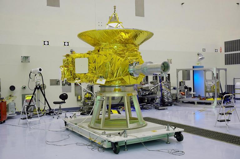
New Horizons is a small spacecraft. It weighs 478 kilograms in total, of which 77 kilograms is the hydrazine fuel, and 30 kilograms the scientific instruments. It measures 0.7×2.1×2.7 meters.


For communication with Earth, the spacecraft is using a 2.1 meter high-gain antenna. The data transfer rate is 38 kilobits per second at Jupiter, and 0.6 to 1.2 kilobits per second at Pluto. The data gathered during the encounter with Pluto will take 9 months to transmit back to Earth.


The scientific payload of the spacecraft draws less than 28 Watts of power. The mission uses a radioisotope thermoelectric generator (RTG) for power generation. The RTG contains 11 kilograms of plutonium dioxide. At the start of the mission, the RTG provided 240 Watts of energy at 30 Volts. Due to the decay of the plutonium, the power output decreases during the mission, and by the time of the Pluto encounter the RTG will only produce about 200 Watts.


The scientific instruments that were selected meet the mission’s goals. NASA set out a list of things it wanted to know about Pluto: the composition and behavior of the atmosphere, the appearance of the surface, the geological structures on the surface of Pluto, etc. The scientific payload contains seven instruments.


Credits: NASA


Ralph is a visible and infrared imager/spectrometer. It will obtain high-resolution color maps and surface composition maps of the surfaces of Pluto and Charon.


Alice is an ultraviolet imaging spectrometer. It will be used to analyze the composition and the structure of Pluto’s atmosphere and to look for atmospheres around Charon and Kuiper Belt Objects (KBOs).


REX is the Radio Science Experiment. It is a passive radiometer that measures atmospheric composition and temperature by using what is called an occultation technique: after passing Pluto, the spacecraft will point its antenna back to Earth and record the transmissions sent by the NASA’s DSN. The alterations of the transmissions caused by Pluto’s atmosphere will be recorded and sent back to Earth for analysis. REX will also be used to measure weak radio emissions from Pluto itself.


LORRI stands for Long Range Reconnaissance Imager. It is a telescopic camera and it will be used to obtain encounter data at long distances, to map Pluto’s far side and to provide high-resolution geologic data. LORRI will take images having 100-meter resolution.


SWAP, the solar wind and plasma spectrometer, stands for Solar Wind Around Pluto. It will measure the atmospheric escape rate and it will observe Pluto’s interaction with solar wind, determining whether Pluto has a magnetosphere or not.


Credits: NASA / JHUAPL

PEPSSI, Pluto Energetic Particle Spectrometer Science Investigation, is an energetic particle spectrometer used to measure the composition and density of plasma (ions) escaping from Pluto’s atmosphere.


SDC is the Student Dust Counter. It is the first scientific instrument built by students mounted on a space probe. It measures the space dust impacting the spacecraft during the voyage across the solar system, recording the count and the size of dust particles. It was built primarily by students from the University of Colorado in Boulder, with supervision from scientists.


If you want to know the present location of the spacecraft, there is a dedicated page on APL that you can visit.


For more information on the New Horizons Mission you can read the New Horizons Missions Guides document on the APL website.


The New Horizons Mission also has a page on Twitter.