OrbitalHub

Where curiosity reaches escape velocity.

Domain is for sale. $50,000,000.00 USD. Direct any inquiries to contact@orbitalhub.com.

Archive for the Spacecraft Design category

October 3, 2011

Micro, nano, pico, and Sprite…

Posted by


Credits: NASA


Dr. Mason Peck, head of the Space Systems Design Studio at Cornell University, answered a few questions for OrbitalHub readers about the Sprite spacecraft. Peck earned a B.S. in Aerospace Engineering from the University of Texas at Austin, and his M.S. and Ph.D. at UCLA as a Howard Hughes Fellow.


A team at the Space Systems Design Studio focuses on Sprite, a simple, feasible design of spacecraft systems printed on small wafers of silicon. This design packages traditional spacecraft systems onto a single silicon microchip.


DJ: Miniaturization brings along quite a few limitations: small payloads and data storage, and much less power available. Why pursue miniaturization when designing a spacecraft?
Mason Peck: In fact, I would disagree with the word–and the concept of–miniaturization. It implies that the goal is to shrink an existing space-system architecture or technology here. Instead, the goals are the following:

– Start from the bottom and work up, i.e. from the level of fundamental technologies, and find out how little it might take to create a space system. If we start by focusing on a mission and consider the problem from the top down, or if we merely try to implement an existing solution at a smaller scale, we miss out on lots of opportunities for innovation.

– Without prejudice, ask how we explore at this small scale? Specifically, how does a very tiny spacecraft exploit the physics of the solar system to navigate, reorient, scavenge power, and the other housekeeping tasks that are fundamental to space exploration.

– And then, with this basic technology concept in place, ask what missions are possible? This approach is known sometimes as “technology push,” where the availability of some new function or performance motivates a new sort of exploration.

So, we expect to discover a kind of parallel universe of exploration possibilities, which has remained hidden from us because of our parochial view of what a spacecraft consists of. I’ll give you some examples in response to your third question.


DJ: How far can miniaturization go?
M.P.: One of our most surprising discoveries is that commercial, off-the-shelf electronics components for mainstream contemporary applications like cell phones and iPods are vastly superior in performance to typical spacecraft electronics. Most people understand that spacecraft electronics are several generations behind the state of the art, and for good reasons such as needing radiation-hard parts, flight-proven reliability, etc. But what’s astonishing is just how far ahead consumer electronics are. We’ll be able to implement GPS-based orbit knowledge, radio communications, and attitude sensing all on about 1 cm^2 of integrated circuitry, using catalog components that anyone can buy. And they’re remarkably cheap, mostly because they’re made in the millions: single-chip GPS receivers, little CMOS cameras, etc. are no more than a few $ each in some cases.

The reliability or survivability of these off-the-shelf components is certain to be much poorer than flight-qualified parts. However, remember that at this scale of size and cost, fabricating and launching thousands or millions is entirely within reach. A single ChipSat may be unreliable, but the cloud of them may offer very high reliability. More than that, a cloud can be understood statistically, with notions like “statistical confidence,” which are very hard to come by when one is building a single, exquisite spacecraft.

A ChipSat will never replace Hubble, but it would not be expected to do so. Instead, ChipSats would form the basis of exploration missions that benefit from a large number of distributed, although coarse, measurements. More generally, this notion of “technology push” introduces a transformative idea for scientists. Instead of posing a science mission that presupposes a spacecraft architecture, let innovation in mission-science objectives couple with engineering innovation. That’s how we’ll do new, remarkable things.


DJ: Can you give some examples of mission scenarios envisioned for swarms of Sprite spacecraft?
M.P.: One of my favorites is that a Sprite may be able to enter a planetary atmosphere without parachutes, rockets, or a heat shield, and yet never burn up. Some of our early work on this problem for Earth’s atmosphere suggests that a 25 micron thick Sprite can reenter without burning up and maintain a cool enough temperature that electronics can continue to operate. So, reentering Sprites can sample the ionosphere, the mesosphere, and on down to the surface of the Earth. We’d get unprecedented measurements of spatial and temporal phenomena like turbulence and particle densities.

Another idea is to place a cloud of these Sprites between the Earth and the Sun, maybe at a so-called Lagrange point, which would be a sort of orbital equilibrium between the two. Each Sprite in the cloud would have the simple task of transmitting a single bit when solar-wind flux or magnetic flux exceeded some threshold, indicating a solar storm. This data would offer a distributed measurement for science, but at least as important it would provide a new type of advance warning of these storms, which can knock out radio communications on Earth.

Yet another application is a bit of science fiction, but it gets us thinking along new lines. Consider a particle accelerator. On Earth, these systems accelerate charged particles like electrons to relativistic velocities so that physicists can study subatomic phenomena. Now imagine the Sprite as a particle. It would be electrostatically charged, like a toy balloon on a dry day, and in that way resembles a very large electron. Could we build a kind of particle accelerator to launch Sprites out of the solar system at very high speed? The Navy already has a railgun that uses electromagnetic effects to launch large masses. Their recent successes show that the concept is perfectly sound. In fact, if you could direct the energy of their 30 kg railgun into a, say, 30 mg Sprite, that’s a factor of 1000 higher speed. Such a Sprite could be the first interstellar explorer. Michio Kaku and I have discussed the wild notion of a ring-shaped Sprite accelerator on the moon or in Jupiter’s orbit (in fact, the idea appeared on his Sci Fi Science TV show). In principle, such a launch system could send a Sprite to the nearest star system in a few decades.


DJ: The small mass and size of a Sprite spacecraft does not leave much room for radiation shielding. Especially during deep space missions, single events can take a spacecraft out of commission. How can Sprite spacecraft compensate for these inherent hazards of space travel?
M.P.: Absolutely right. Radiation will degrade the Sprite until it stops functioning. The easiest solution is simply to produce a rad-hardened chip. They’re not uncommon, although it’s expensive to design and build them. But it can be done, and amortizing that cost over millions of Sprites would make doing so a lot more appealing than how it’s done now, where we go to all that effort for a relatively small number of chips. But if you don’t want to get into rad hardening, remember that this effect is a statistical one. So, using a large enough number of Sprites for a mission would be a way to ensure that a desired fraction of them survive, even though a large number would fail. Again, we could design in this statistical reliability. And the more you use, the more reliably the mission meets its objectives.


DJ: Sprite is by definition a propellantless spacecraft. What type of propulsion can be employed?
M.P.: I wouldn’t be against trying to implement traditional propulsion at this scale. In fact, it’s been done, with mixed success. But the reason to pursue propellantless technologies is that chemical propulsion does not scale down well.

We find that several approaches do scale well. First, solar sailing is a clear winner. With a thin but still rigid silicon wafer, we can get performance benefits similar to the vast solar sails that have been proposed, but with the important advantage that the sail is not a floppy mess, difficult to deploy and steer around. The acceleration of a solar-sail Sprite increases with 1/L, where L is the length scale. As long as there are no limitations on thickness, a uniformly shrunken solar sail works better than its larger analogue. For example, a 1m solar sail accelerates 10x as fast as a 10m solar sail, as long as the thickness scales proportionately. That proportionate scaling may be tough to achieve, but what’s easy is the stiffness: a 25 micron Sprite is stiff enough that it needs no deployable booms or trusses, and it’s therefore effectively thinner (less mass for the area) than the larger sails.

A little harder to implement but even more intriguing is electrodynamic tether technology. Sprite sends a current through a wire that extends from the spacecraft, grounded in the ionospheric plasma. The current interacts with the Earth’s magnetic field, like the windings in an electric motor, producing a force. That force can accelerate the spacecraft. Just like the solar-sailing example, an ED tether is a lot more convenient when it’s shorter: it’s basically a rod, not a floppy string. The dynamics-related problems that the Space Shuttle tether experiments encountered would not arise here.


DJ: How many Sprite spacecraft are currently deployed and what kind of payloads do they have?
M.P.: There are three prototypes on the outside of the International Space Station. They’re not free-flying. They’re self-powered with solar cells, and they have their own on-board computers, radios, and other circuitry. They are their own payload in the sense that if they communicate, we’ll be able to confirm that Sprite’s unique communications architecture is a valid design. We didn’t have time (and we had no money, in fact) for a science payload per se.


DJ: Swarms of hundreds of decommissioned Sprite spacecraft orbiting the Earth could make mission flight control rooms very nervous. Are there any post-mission disposal methods considered for Sprite missions?
M.P.: Yes and no. Space debris is certainly a risk, but Sprites do not have to be debris. In low-earth orbit, their unique flight dynamics mean that aerodynamic drag very quickly pulls them back into the atmosphere. Specifically, a 325 km orbit would decay in about 2 days. Even at 500 km, they would reenter in weeks, at most. If they burn up, that’s that. If they don’t, it’s because they’re so delicate that they would never hurt anyone even if one were to land on a person on the ground. So, they clean up after themselves.


DJ: What are the areas with room for improvement in the design and manufacturing of chip-sized satellites?
M.P.: The next step will be that the design will transition from discrete parts to a single, application-specific integrated circuit (ASIC). That’s the real objective. It would be far lighter, less power-hungry, and more maneuverable than the current prototypes on ISS.


Credits: Zac Manchester


To find out more about the Sprite Spacecraft, Dr. Mason Peck, and his team at Cornell University, please visit the Space Systems Design Studio webpage. Paul Gilster of Centauri Dreams has also covered this topic in ’Smart Dust’ and Solar Sails and Tiny Spacecraft Point to Future Sails.


December 10, 2010

Houston, The Cheese Has Landed!

Posted by


Credits: NASA/Tony Gray and Kevin O’Connell


… or to be more exact, the cheese re-entered the Earth’s atmosphere and performed a successful splashdown in the Pacific Ocean onboard SpaceX’s Dragon spacecraft on December 8, 2010. The same day, roughly three and a half hours earlier, the Dragon spacecraft was placed into low Earth orbit by a Falcon 9 launch vehicle, which lifted off from Cape Canaveral Air Force Station Space Launch Complex 40 on COTS Demo Flight 1.


On this flight, several key components of the Dragon spacecraft were tested: the Draco thrusters, which control the spacecraft throughout flight and reentry; the PICA-X heat shield, which is the SpaceX variant of NASA’s phenolic impregnated carbon ablator (PICA) heat shield; avionics; telemetry; and the drogue and main parachutes used for stabilization and landing.


The Dragon spacecraft is capable of fully autonomous rendezvous and docking, can carry over three metric tons in each of the pressurized and unpressurized sections, and it supports five to seven passengers in crew configuration. SpaceX’s primary goal for this demo flight was to collect as much data as possible.


Before the launch, Elon Musk, SpaceX CEO and CTO, made the following statement:

“When Dragon returns, whether on this mission or a future one, it will herald the dawn of an incredibly exciting new era in space travel. This will be the first new American human capable spacecraft to travel to orbit and back since the Space Shuttle took flight three decades ago. The success of the NASA COTS/CRS program shows that it is possible to return to the fast pace of progress that took place during the Apollo era, but using only a tiny fraction of the resources. If COTS/CRS continues to achieve the milestones that many considered impossible, thanks in large part to the skill of the program management team at NASA, it should be recognized as one of the most effective public-private partnerships in history.”


February 21, 2010

CryoSat-2

Posted by


Credits: ESA – P. Carril


In 2007, projections of sea level rise made by the Fourth Assessment Report of the Intergovernmental Panel on Climate Change were in the range of 28–43 cm by 2100, but there are new projections of the sea level rise that are in the order of 1.4 m.


While the trend is quite obvious, it is very important to be able to make accurate predictions.


Cryosat has been designed to measure the ice thickness on land and also at sea, and will provide enough data so that a precise rate of change of the ice thickness can be determined. A better understanding of how the volume of ice on Earth is changing will also be possible.


The declared primary goals of the CryoSat mission are to determine the regional trends in Arctic perennial sea-ice thickness and mass, and to determine the contribution that the Antarctic and Greenland ice sheets are making to mean global rise in sea level. Cryosat will also measure the variations in the thickness of Earth’s polar caps and glaciers. The spacecraft will be operational for a minimum of three years.


Credits: ESA/P. Carril


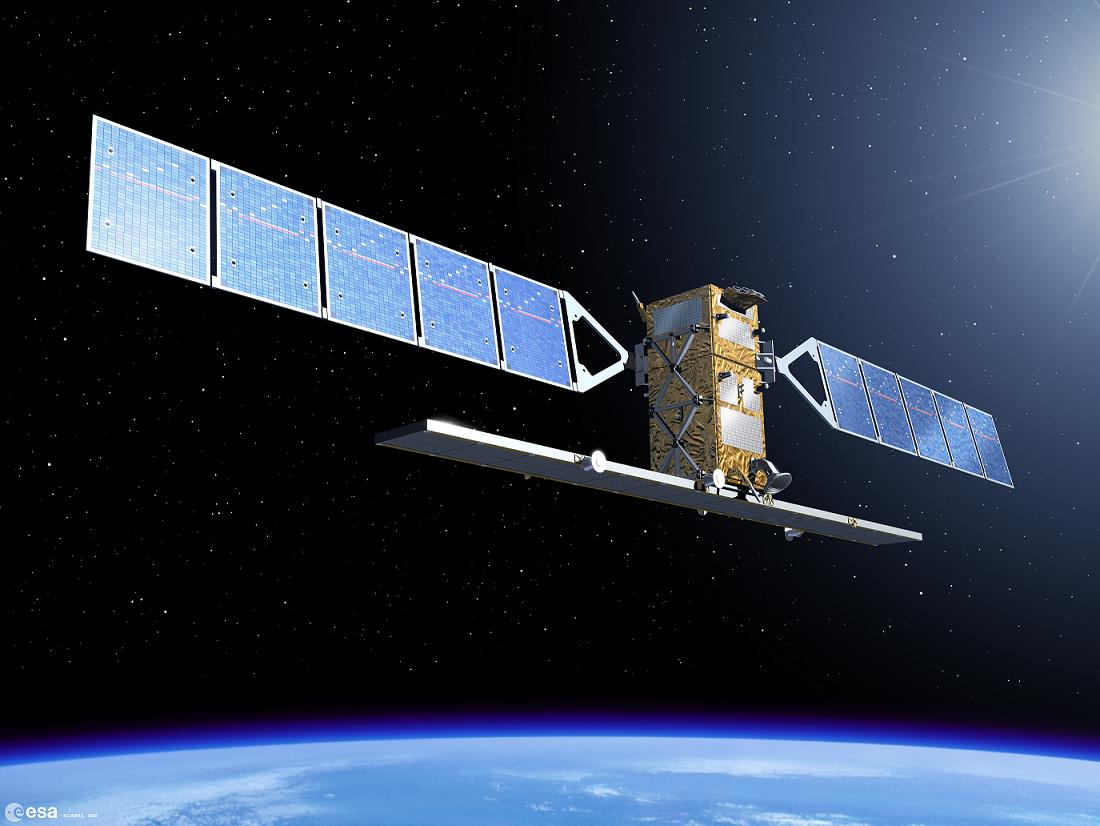
The spacecraft has a launch mass of 720 kg, of which 23 kg is the fuel required for orbital maneuvers and attitude corrections. The overall size of the spacecraft is 4.6 m x 2.34 m. Two solar panels are attached to the spacecraft’s body and provide a maximum of 800 W of power. As the CryoSat-2 orbit is not Sun-synchronous, providing enough power to the scientific payload has been a considerable challenge.


The operational orbit will be a 717 km non Sun-synchronous orbit with a 92 degree inclination.


The primary payload of the CryoSat-2 spacecraft is the SAR/Interferometric Radar Altimeter (SIRAL). In order to have the position of the spacecraft accurately tracked, a radio receiver called Doppler Orbit and Radio Positioning Integration by Satellite (DORIS) and a laser retro-reflector are part of the payload as well. A global network of laser ranging stations (the International Laser Ranging Service or ILRS for short) will support the mission. Three star-trackers will ensure a proper orientation of the spacecraft.


Using the Synthetic Aperture technique, CryoSat-2 measurements taken by SIRAL will have a 250 m resolution in the along-track direction. The instrument is designed to operate in three measurement modes: Low Resolution Mode (LRM) mostly over the oceans, Synthetic Aperture Radar (SAR) mode over sea-ice areas, and SAR Interferometric (SARIn) mode over steeply sloping ice-sheet margins, small ice caps, and mountain glaciers.


Credits: ESA – AOES Medialab


CryoSat-2 will be placed in orbit by a Dnepr launch vehicle. With a lift-off mass of 211 tons, Dnepr is 34 m long and 3 m in diameter, and has three stages that use hypergolic liquid propellants (N2O4 nitrogen peroxide and UDMH unsymmetrical dimethylhydrazine). In addition, there are Dnepr configurations with a third and a fourth stage for missions that require more energy. The launch vehicle is based on an ICMB designated as SS-18 Satan by NATO. The development and commercial operation of the Dnepr Space Launch System is managed by the International Space Company (ISC) Kosmotras. Dnepr can lift 4,500 kg to low Earth orbit (LEO) or 2,300 kg to a 98 degree Sun-synchronous orbit. Among other satellites launched by Dnepr are Demeter, Genesis I, Genesis II, and THEOS. Dnepr, carrying Cryosat-2, will lift off from Baikonur Cosmodrome in Kazakhstan.


The Rockot launch vehicle that attempted the orbiting of the first CryoSat mission, on October 8, 2005, failed to reach orbit. Due to faults in the onboard software, the second stage engine of the launcher did not shut down. The mission was terminated when the launch vehicle exceeded the flight envelope limit. The Rockot second stage/Breeze-KM/CryoSat stack crashed somewhere in the Arctic Ocean.


You can find more information about Cryosat-2 on ESA’s dedicated website. The Cryosat-2 mission EADS team also has a blog on EADS Astrium website. Check out the latest updates from Baikonur brought to you by Klaus Jäger (Astrium Spacecraft Launch Manager) and Edmund Paul (Astrium Spacecraft Operations Manager). A presentation of the SIRAL-2 instrument is available on Thales Group’s website.


January 17, 2010

Sentinel

Posted by


Credits: ESA – P.Carril


The European Union’s Global Monitoring for Environment and Security (GMES) initiative was born as the result of a growing need for accurate and accessible information about the environment, the effects of climate change, and civil security. GMES uses as its main information feed the data collected by satellites developed by ESA. Data is also collected by instruments carried by aircraft, floating in the ocean, or located on the ground.


GMES provides services that can be grouped into five main categories: land management, marine environment, atmosphere, aid emergency response, and security.


There are five Sentinel missions designed as components of the GMES initiative. These missions will complement the national initiatives of the EU members involved. The missions will collect data for land and ocean monitoring, and atmospheric composition monitoring, making use of all-weather radar and optical imaging. Each of the Sentinel missions is based on a constellation of two satellites.


Sentinel-1 is an all-weather radar-imaging mission. The satellites will have polar orbits and collect data for the GMES land and ocean services. The first satellite is scheduled for launch in 2012. Sentinel-1 will ensure the continuity of Synthetic Aperture Radar (SAR) applications, taking over from systems carried by ERS-1, ERS-2, Envisat, and Radarsat. Sentinel-1 satellites will be carried to orbit by Soyuz launch vehicles lifting off from Kourou.


Sentinel-2 will provide high-resolution multi-spectral imagery of vegetation, soil, and water, and will cover inland waterways and coastal areas. Sentinel-2 is designed for the data continuity of missions like Landsat or SPOT (Satellite Pour l’Observation de la Terre). Each satellite will carry a Multi-Spectral Imager (MSI) that can ‘see’ in thirteen spectral bands spanning from the visible and near infrared (VNIR) to the shortwave infrared (SWIR). The first Sentinel-2 is planned to launch in 2013. Vega will provide launch services for Sentinel-2 missions.


Credits: ESA – P.Carril


Sentinel-3 will determine parameters such as sea-surface topography and sea and land surface temperature. It will also determine ocean and land colour with high accuracy. The first Sentinel-3 satellite is expected to reach orbit in 2013. The spacecraft bus has a three-meter accuracy real-time orbit determination capability based on GPS and Kalman filtering.


Sentinel-4 is devoted to atmospheric monitoring and it will consist of payloads carried by Meteosat Third Generation (MTG) satellites that are planned to launch in 2017 and 2024. Sentinel-5 will be used for atmospheric monitoring as well. The payload will be carried by a post-EUMETSAT Polar System (EPS) spacecraft, planned to launch in 2020. A Sentinel-5 precursor will ensure that no data gap will exist between the Envisat missions and Sentinel-5.


You can find out more about the GMES initiative and the Sentinel missions on a dedicated page on ESA’s website.


June 19, 2009

SMOS

Posted by


Credits: ESA-AOES Medialab


The Soil Moisture and Ocean Salinity (SMOS) mission, which is the second Earth Explorer Opportunity mission to be developed as part of ESA’s Living Planet Program, will provide global maps of moisture over the Earth’s landmasses and salinity over the oceans. These observations will improve our understanding of hydrology and ocean circulation patterns.


The science objectives for the SMOS mission are global monitoring of surface soil moisture and surface salinity over oceans, and improving the characterization of ice and snow-covered surfaces.


The SMOS satellite is built around a standard spacecraft bus called Proteus, which was developed by the French space agency CNES (Centre National d’Etudes Spatiales) and Alcatel Alenia Space. Proteus measures one cubic meter and plays the role of a service module, hosting all the subsystems that are required for the satellite to function.


A GPS receiver collects satellite position information. A hydrazine monopropellant system consisting of four 1-Newton thrusters, which are mounted on the base of the spacecraft, provides the thrust for orbit control. Three 2-axis gyroscopes and four small reaction wheels control the attitude of the satellite. A star tracker also provides accurate attitude information for instrument measurements.


The solar panels can produce up to 900 W, covering the 525 W maximum payload consumption. During eclipse periods, the satellite uses a 78 AH Li-ion battery. SMOS has a launch mass of 658 kg: a 275 kg platform, 355 kg payload, and 28 kg of fuel.


The SMOS satellite will deploy a new type of scientific instrument in space: a microwave imaging radiometer that operates between 1,400 – 1,427 MHz (L-band). The instrument is called Microwave Imaging Radiometer using Aperture Synthesis, or MIRAS, for short. MIRAS consists of a central structure and three deployable arms, and uses 69 antenna-receivers (LICEFs) for measuring microwave radiation emitted from the surface of the Earth. The instrument is the result of almost ten years of research and development.


Credits: ESA-AOES Medialab


The data collected by MIRAS needs to go through a validation process. The radiation received by the instrument is a function that depends not only on soil moisture and ocean salinity, other effects need to be considered when instrument data is converted into units of salinity and moisture.


Factors that have to be considered are the distribution of vegetation, the litter layer, the soil type, the varying roughness of the surface, and the physical temperature of the surface of the land and sea.


In order to quantify the effects of factors mentioned above, dedicated campaign activities were conducted. Ground-based and airborne instruments similar to the one mounted on SMOS were used to collect data that was correlated with in-situ observations made by large ground teams. Long-term observations were carried out from an oilrig platform in the Mediterranean and at the Concordia Station in Antarctica.


The Committee on Earth Observation Satellites (CEOS) has defined a number of levels for the SMOS Mission Data Products. They range from Raw Data to Level-3 Data Products, which are Soil Moisture and Ocean Salinity global maps. Level-3 data will be available from the SMOS Level 3/4 Processing Center in Spain.


Eurockot will provide the launch services for the SMOS mission. A Rockot launcher, which is derived from a Russian Intercontinental Ballistic Missile (ICBM) SS-19, will lift off from the Plesetsk Cosmodrome, 800 km north of Moscow. The Rockot launcher will inject the satellite in a 758 km quasi-circular orbit.


The CNES Satellite Operations Ground Segment and ESA/CDTI (Centro para el Desarrollo Technologico Industrial) Data Processing Ground Segment will be responsible for the SMOS mission ground segment.


Initially scheduled for 2008, the launch of the Earth Explorer SMOS satellite will take place some time from July to October 2009.


You can find more details about SMOS on the dedicated page on ESA’s web site.


May 18, 2009

Glory In The Sky

Posted by


Credits: NASA


Understanding the Earth’s energy balance is important in order to anticipate changes to the climate. The Glory mission will make a significant contribution towards explaining the Earth’s energy budget.


There are two scientific objectives set for the Glory mission: mapping the global distribution, properties, and chemical composition of natural and anthropogenic aerosols, and the continued measurement of solar irradiance. Both will lead to a reliable quantification of the aerosol and Sun’s direct and indirect effects on Earth’s climate.


The Glory spacecraft uses Orbital’s LEOStar bus design. The structure of the bus consists of an octagonal aluminum space frame with two 750 W deployable solar panels and a 100 W body-mounted solar panel. Glory will have a launch mass of 545 kg.


Forty-five kilograms of hydrazine powers a propulsion module, which will provide orbital maneuvering and attitude control capabilities for the projected 36-month lifespan of the spacecraft. The spacecraft bus also provides 3-axis stabilization, X-band/S-band RF communication capabilities, payload power, command, telemetry, science data interfaces, and an attitude control subsystem to support science instrument requirements.


Credits: NASA


Three instruments will be mounted on Glory: the Aerosol Polarimetry Sensor (APS), the Total Irradiance Monitor (TIM), and the Cloud Camera Sensor Package (CCSP).


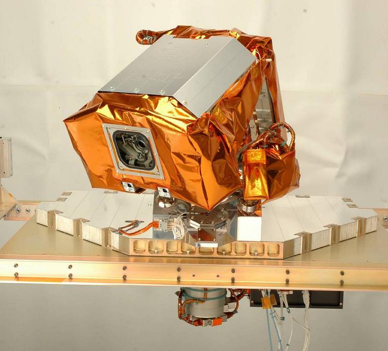
The APS will map the global aerosol distribution by measuring the light reflected within the solar reflective spectrum region of Earth’s atmosphere (which is visible, near- infrared, and short-wave infrared light scattered from aerosols).


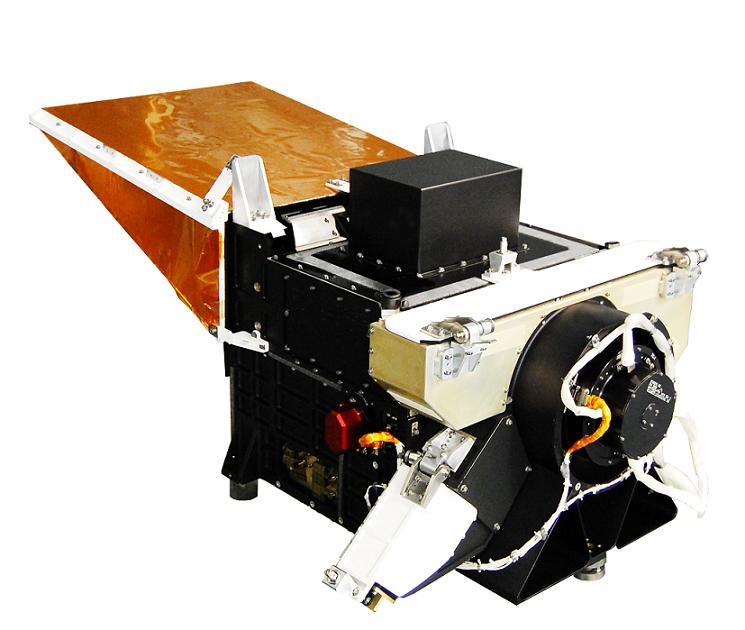
TIM will collect measurements of the total solar irradiance (TSI), which is the amount of solar radiation in the Earth’s atmosphere over a period of time. TIM consists of four electrical substitution radiometers (ESRs) that are pointed towards the Sun, independently of the position of the spacecraft. TIM was developed by the University of Colorado’s Laboratory for Atmospheric and Space Physics (LASP). TIM inherited the design of an instrument flown on SORCE satellite, which was launched in 2003. A presentation of the TIM design and on-orbit functionality was published by Greg Kopp, George Lawrence, and Gary Rottman of LASP.


The CCSP will be used to distinguish between measurements done on clear or cloud- filled areas, as clouds can have a significant impact on the quality of the measurements. CCSP is a dual-band (blue and near-infrared) imager that uses non-scanning detector arrays similar to those used in star trackers.


Credits: NASA


Glory will be launched from Vandenberg Air Force Base, California, on top of a Taurus XL launch vehicle. The operational orbit is a 705 km, sun-synchronous, circular, 98.2 degree inclination, low Earth orbit (LEO). The launch date is set for Fall 2009.


Read more about Glory at the Glory Mission page on NASA Goddard Space Flight Center’s website. A Glory Fact Sheet is also available on Orbital Sciences Corporation’s website.