OrbitalHub

The place where space exploration, science, and engineering meet

Domain is for sale. $50,000,000.00 USD. Direct any inquiries to contact@orbitalhub.com.

09-7-10

How Tough is Life in LEO?

Posted by


Credits: NASA


In a nutshell, it is really tough! The higher you go, more bad things can happen to you… the increasingly rarefied air, freezing temperatures, ionized atoms, radiation, and space debris make life challenging. So, besides thinking of how to place spacecraft in orbit, engineers must consider all of the factors mentioned above (and much more) when designing a spacecraft.


The space environment (the vacuum, the radiation, the space debris, etc.) definitely poses big challenges to spacecraft design engineers. From 1971 to 1989, more than 2,700 spacecraft anomalies related to interactions with the space environment were recorded. These interactions with the space environment are called space environment effects and the changes in the space environment define what is called the space weather. Believe it or not, there are dedicated programs aimed at developing the ability to predict these changes in the same way the weather forecasting does for terrestrial weather. The Space Weather program was formed in the mid-1990s by the National Science Foundation (NSF). The Europeans developed a similar program under the umbrella of the European Space Agency (ESA).


The space environment effects can be grouped into several categories. Such categories include: vacuum, neutral, plasma, radiation, and micrometeorid/orbital debris. So, basically, we can discuss the effects of the vacuum environment, the neutral environment, etc. Each one of these environments interact with the subsystems that comprise a spacecraft: the propulsion system that provides the means of maintaining a certain orbit or attitude, the electrical power system that provides power to the rest of the subsystems onboard, the thermal control system, the attitude and orbital determination and control system, etc.


The vacuum environment imposes challenges when it comes to designing the structure, choosing the materials, and defining a strategy for thermal control. The pressure differential between the inside and the outside of a manned spacecraft is tremendous (around 350 km above the surface of the Earth, the pressure is ten orders of magnitude less). The lack of atmosphere translates into the fact that the spacecraft will have to deal with solar ultraviolet (UV) radiation (the UV radiation is energetic enough to degrade material properties). Also, the spacecraft can only cool itself by conduction or radiation.


Credits: NASA


Even if very rarefied, the neutral atmosphere in low Earth orbit is dense enough to cause a significant atmospheric drag force. The atoms can physically sputter material from surfaces and even cause erosion. All these mechanical and chemical interactions depend on the atmospheric density.


In low Earth orbit, the solar UV radiation ionizes the oxygen and nitrogen atoms. This environment, known as the plasma environment, can give rise to very interesting effects, like spacecraft charging and arcing between regions of differing potentials.


By far, the most dangerous environment in Earth orbit is the radiation environment. In the regions of charged particles, known as trapped radiation belts, particles with energy levels in the order of MeV pass through the surface layer and interact with the materials inside the spacecraft. Present shielding technology cannot protect living organisms inside a spacecraft in these regions.


Micrometeoroids and orbital debris are a cause of great concern to spacecraft design engineers and spacecraft operators as the kinetic energies associated with impacts at orbital velocities are very high. The main effect on spacecraft in this case is the physical damage upon impact. Other effects include surface erosion, ejecta resulted from impacts, changes in thermal control properties, and generation of electro-magnetic impulses (EMIs).


As most of the characteristics of the space environment were determined by remote observations or during short duration missions, one long duration mission was necessary to verify and validate these measurements.


In April 1984, the Space Shuttle Challenger placed into low Earth orbit (LEO) a spacecraft carrying a number of experiments for the purpose of characterizing the low Earth orbit environment. The spacecraft (known as the Long Duration Exposure Facility, or LDEF for short) was a twelve-sided cylindrical structure three-axis stabilized in order to ensure an accurate environmental exposure. The spacecraft was supposed to spend one year in orbit, but just before the planned retrieval, the Space Shuttle fleet was grounded as a result of the Challenger accident on January 28, 1986.


The spacecraft was returned to Earth by the Space Shuttle Columbia in January 1990. After almost six years in low Earth orbit, the results of the experiments onboard the facility contributed a great deal to the understanding of interactions between artificial objects and the environment in low Earth orbit.


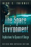
You can find all the above in much more detail in Alan Tribble’s book The Space Environment – Implications for Spacecraft Design. Alan Tribble presents an excellent account of the effects the space environment can have on operational spacecraft. The book offers a unique perspective, as it combines the study of the space environment with spacecraft design engineering. .


Alan Tribble spent over ten years designing spacecraft. He is a technical project manager in the International Software Defined Radios group for Rockwell Collins.


  • Facebook
  • Google
  • Slashdot
  • Reddit
  • Live
  • TwitThis
02-21-10

CryoSat-2

Posted by


Credits: ESA – P. Carril


In 2007, projections of sea level rise made by the Fourth Assessment Report of the Intergovernmental Panel on Climate Change were in the range of 28–43 cm by 2100, but there are new projections of the sea level rise that are in the order of 1.4 m.


While the trend is quite obvious, it is very important to be able to make accurate predictions.


Cryosat has been designed to measure the ice thickness on land and also at sea, and will provide enough data so that a precise rate of change of the ice thickness can be determined. A better understanding of how the volume of ice on Earth is changing will also be possible.


The declared primary goals of the CryoSat mission are to determine the regional trends in Arctic perennial sea-ice thickness and mass, and to determine the contribution that the Antarctic and Greenland ice sheets are making to mean global rise in sea level. Cryosat will also measure the variations in the thickness of Earth’s polar caps and glaciers. The spacecraft will be operational for a minimum of three years.


Credits: ESA/P. Carril


The spacecraft has a launch mass of 720 kg, of which 23 kg is the fuel required for orbital maneuvers and attitude corrections. The overall size of the spacecraft is 4.6 m x 2.34 m. Two solar panels are attached to the spacecraft’s body and provide a maximum of 800 W of power. As the CryoSat-2 orbit is not Sun-synchronous, providing enough power to the scientific payload has been a considerable challenge.


The operational orbit will be a 717 km non Sun-synchronous orbit with a 92 degree inclination.


The primary payload of the CryoSat-2 spacecraft is the SAR/Interferometric Radar Altimeter (SIRAL). In order to have the position of the spacecraft accurately tracked, a radio receiver called Doppler Orbit and Radio Positioning Integration by Satellite (DORIS) and a laser retro-reflector are part of the payload as well. A global network of laser ranging stations (the International Laser Ranging Service or ILRS for short) will support the mission. Three star-trackers will ensure a proper orientation of the spacecraft.


Using the Synthetic Aperture technique, CryoSat-2 measurements taken by SIRAL will have a 250 m resolution in the along-track direction. The instrument is designed to operate in three measurement modes: Low Resolution Mode (LRM) mostly over the oceans, Synthetic Aperture Radar (SAR) mode over sea-ice areas, and SAR Interferometric (SARIn) mode over steeply sloping ice-sheet margins, small ice caps, and mountain glaciers.


Credits: ESA – AOES Medialab


CryoSat-2 will be placed in orbit by a Dnepr launch vehicle. With a lift-off mass of 211 tons, Dnepr is 34 m long and 3 m in diameter, and has three stages that use hypergolic liquid propellants (N2O4 nitrogen peroxide and UDMH unsymmetrical dimethylhydrazine). In addition, there are Dnepr configurations with a third and a fourth stage for missions that require more energy. The launch vehicle is based on an ICMB designated as SS-18 Satan by NATO. The development and commercial operation of the Dnepr Space Launch System is managed by the International Space Company (ISC) Kosmotras. Dnepr can lift 4,500 kg to low Earth orbit (LEO) or 2,300 kg to a 98 degree Sun-synchronous orbit. Among other satellites launched by Dnepr are Demeter, Genesis I, Genesis II, and THEOS. Dnepr, carrying Cryosat-2, will lift off from Baikonur Cosmodrome in Kazakhstan.


The Rockot launch vehicle that attempted the orbiting of the first CryoSat mission, on October 8, 2005, failed to reach orbit. Due to faults in the onboard software, the second stage engine of the launcher did not shut down. The mission was terminated when the launch vehicle exceeded the flight envelope limit. The Rockot second stage/Breeze-KM/CryoSat stack crashed somewhere in the Arctic Ocean.


You can find more information about Cryosat-2 on ESA’s dedicated website. The Cryosat-2 mission EADS team also has a blog on EADS Astrium website. Check out the latest updates from Baikonur brought to you by Klaus Jäger (Astrium Spacecraft Launch Manager) and Edmund Paul (Astrium Spacecraft Operations Manager). A presentation of the SIRAL-2 instrument is available on Thales Group’s website.


  • Facebook
  • Google
  • Slashdot
  • Reddit
  • Live
  • TwitThis
02-7-10

Solar Dynamics Observatory

Posted by


Credits: NASA/Goddard Space Flight Center Scientific Visualization Studio


Predictions of space weather are important as the effects of magnetic storms can be very significant: disruptions in radio communications, radiation hazards to astronauts in LEO, and power lines surges, just to name a few. The goal of NASA’s Living With a Star (LWS) Program is to understand the changing Sun and its effects on the Solar System. The Solar Dynamics Observatory (SDO) is one of NASA’s LWS missions.


SDO will take measurements of the solar activity. There are seven science questions SDO will try to answer. Among them, what is the mechanism that drives the cycles of solar activity? How do the EUV variations relate to the magnetic activity of the Sun? Is it possible to make predictions regarding the space weather and climate? The last question, if answered, will make choosing the launch windows for future interplanetary manned missions an easier task.


The spacecraft is 2.2 x 2.2 x 4.5 m and 3-axis stabilized. At launch, it has a mass of 3200 kg (270 kg the payload and 1400 kg the fuel). The solar panels are 6.5 m across, cover 6.6 m2, and produce up to 1540 W of power.


Credits: NASA


SDO carries three instruments: the Atmospheric Imaging Assembly (AIA), EUV Variability Experiment (EVE), and the Helioseismic and Magnetic Imager (HMI). The instruments will take measurements that will reveal at a very high rate the variations of the Sun.


The HMI was developed at Stanford University and it will extend the SOHO/MDI instrument. The HMI will help to study the origin of variability and the various components of the magnetic activity of the Sun. The measurements aim at understanding the origin and evolution of sunspots, sources and drivers of solar activity and disturbances, connections between the internal processes and the dynamics of the corona and the heliosphere.


You can find more information about the instrument on the HMI page on Stanford University’s web site.


The AIA will capture images of the solar atmosphere in ten wavelengths every ten seconds. The data collected by the instrument will improve the understanding of the activity in the solar atmosphere. The instrument was developed by Lockheed Martin.


EVE was developed at University of Colorado at Boulder. EVE will measure the solar extreme ultraviolet irradiance.


The SDO will launch aboard an Atlas V launch vehicle from SLC 41 at Cape Canaveral. SDO will operate on a geosynchronous orbit, which will allow continuous observations of the Sun. The orbit will also allow a continuous contact with a single dedicated ground station. The high data acquisition rate required such a mission profile, as a large on-board storage system would add to the overall complexity of the system.


You can find more information about SDO on NASA’s website.


  • Facebook
  • Google
  • Slashdot
  • Reddit
  • Live
  • TwitThis
05-18-09

Glory In The Sky

Posted by


Credits: NASA


Understanding the Earth’s energy balance is important in order to anticipate changes to the climate. The Glory mission will make a significant contribution towards explaining the Earth’s energy budget.


There are two scientific objectives set for the Glory mission: mapping the global distribution, properties, and chemical composition of natural and anthropogenic aerosols, and the continued measurement of solar irradiance. Both will lead to a reliable quantification of the aerosol and Sun’s direct and indirect effects on Earth’s climate.


The Glory spacecraft uses Orbital’s LEOStar bus design. The structure of the bus consists of an octagonal aluminum space frame with two 750 W deployable solar panels and a 100 W body-mounted solar panel. Glory will have a launch mass of 545 kg.


Forty-five kilograms of hydrazine powers a propulsion module, which will provide orbital maneuvering and attitude control capabilities for the projected 36-month lifespan of the spacecraft. The spacecraft bus also provides 3-axis stabilization, X-band/S-band RF communication capabilities, payload power, command, telemetry, science data interfaces, and an attitude control subsystem to support science instrument requirements.


Credits: NASA


Three instruments will be mounted on Glory: the Aerosol Polarimetry Sensor (APS), the Total Irradiance Monitor (TIM), and the Cloud Camera Sensor Package (CCSP).


The APS will map the global aerosol distribution by measuring the light reflected within the solar reflective spectrum region of Earth’s atmosphere (which is visible, near- infrared, and short-wave infrared light scattered from aerosols).


TIM will collect measurements of the total solar irradiance (TSI), which is the amount of solar radiation in the Earth’s atmosphere over a period of time. TIM consists of four electrical substitution radiometers (ESRs) that are pointed towards the Sun, independently of the position of the spacecraft. TIM was developed by the University of Colorado’s Laboratory for Atmospheric and Space Physics (LASP). TIM inherited the design of an instrument flown on SORCE satellite, which was launched in 2003. A presentation of the TIM design and on-orbit functionality was published by Greg Kopp, George Lawrence, and Gary Rottman of LASP.


The CCSP will be used to distinguish between measurements done on clear or cloud- filled areas, as clouds can have a significant impact on the quality of the measurements. CCSP is a dual-band (blue and near-infrared) imager that uses non-scanning detector arrays similar to those used in star trackers.


Credits: NASA


Glory will be launched from Vandenberg Air Force Base, California, on top of a Taurus XL launch vehicle. The operational orbit is a 705 km, sun-synchronous, circular, 98.2 degree inclination, low Earth orbit (LEO). The launch date is set for Fall 2009.


Read more about Glory at the Glory Mission page on NASA Goddard Space Flight Center’s website. A Glory Fact Sheet is also available on Orbital Sciences Corporation’s website.


  • Facebook
  • Google
  • Slashdot
  • Reddit
  • Live
  • TwitThis
04-17-09

Delta II

Posted by


Credits: NASA/MSFC


Delta II is a space launch system operated by United Launch Alliance (ULA), which was initially built by McDonnell Douglas, and by Boeing Integrated Defense Systems after McDonnell Douglas merged with Boeing in 1997.


As any other early space launch system, it evolved from a ballistic missile. In the 1960s, the Thor intermediate-range ballistic missile was modified to become the Delta launch vehicle. In 1981, after being operated for 24 years, Delta production was halted due to a change in U.S. space policy. However, in 1986, after the Challenger accident, it was decided that the Space Shuttle fleet would not carry commercial payloads anymore, paving the way for the return of the Delta launch vehicle. Delta II had its maiden flight on February 14, 1989.


Delta II launch vehicle is 38.2 to 39 m long, with a diameter of 2.44 m, and a mass that can range from 151,700 to 231,870 kg, depending on configuration. Delta II can be configured with two or three stages.


Delta II can inject a payload having a mass of 2,700 to 6,100 kg in low Earth orbit (LEO). Payloads deployed to Geosynchronous Transfer Orbit (GTO) can have a mass from 900 to 2,170 kg.


The first stage, Thor/Delta XLT-C, is powered by one Pratt & Whitney Rocketdyne RS-27A liquid fuel engine. The RS-27A engine is fueled by RP-1 and liquid oxygen. The RS-27A engine provides around 1,000 kN of thrust.


Credits: NASA


The solid boosters are used to increase the thrust of the launch vehicle. The first solid boosters used by Delta II 6000 series were Castor 4A motors. The 7000 and 7000 Heavy series use GEM 40 and GEM 46 solid motors respectively. The increase in thrust from Castor 4A to GEM 46 is substantial, from 480 kN to 630 kN.


Stage two, Delta K, is powered by a hypergolic restartable Aerojet AJ10-118K engine that can provide 43 kN. The AJ10-118K can fire more than once in order to insert the payload into LEO. The engine uses dinitrogen tetroxide as oxidizer and aerozine 50 (which is a mix of hydrazine and unsymmetrical dimethylhydrazine) as fuel. Besides having hard to pronounce names, the oxidizer and the fuel are very toxic and corrosive. The second stage contains the flight control system, which is a combined inertial system and guidance system.


The third stage, if present in the configuration, is a Payload Assist Module (PAM). This stage is powered by an ATK-Thiokol motor, which provides the velocity change needed for missions beyond Earth orbit. The stage has no active guidance control and it is spin-stabilized.


The de-spin mechanism used to slow the spin of the spacecraft after the burn and before the stage separation is a yo-yo de-spin mechanism. This mechanism consists of two cables with weights on the ends. The weights are released and the angular momentum transferred from the stage reduces the spin to a value that can be controlled by the attitude control system of the spacecraft.


Delta II can launch single, dual, or multiple payloads during the same mission. There are three fairing sizes available: composite 3-meter diameter, aluminum 2.9-meter diameter, and stretched composite 3-meter diameter.


Credits: NASA


Delta II is assembled on the launch pad. After hoisting the first stage into position, the solid boosters are hoisted and mated with the first stage. The second stage is then hoisted atop the first stage.


Delta II launch vehicles have a four-digit naming system. The first digit can be either 6 or 7, designating the 6000 or 7000 series. The second digit indicates the number of solid boosters used for the mission. Delta II can have three, four, or nine solid boosters strapped to the first stage. The third digit denotes the engine type used for the second stage. This digit is two for 6000 and 7000 series Delta II, which indicates the Aerojet A10 engine. The last digit designates the type of the third stage. Zero means that no third stage is used, whereas five indicates a third stage powered by a Star 48B solid motor, and 6 marks a third stage powered by a Star 37FM motor. A Delta II 7426 has 4 solid boosters and a third stage powered by a Star 37FM motor.


Delta II proved to be a very reliable Expendable Launch Vehicle (ELV). Some NASA missions that used Delta II as launch vehicle include: Mars Global Surveyor, Mars Pathfinder, Mars Exploration Rovers (MER-A Spirit and MER-B Opportunity), Mars Phoenix Lander, Dawn, STEREO, and Kepler.


After long years of service, Delta II is getting close to retirement. The final mission for Delta II is currently scheduled for 2011.


You can find more information about the Delta launch vehicles on the Delta web page on Boeing’s web site.


  • Facebook
  • Google
  • Slashdot
  • Reddit
  • Live
  • TwitThis
03-21-09

Taurus

Posted by


Credits: Orbital


Taurus is a four-stage, inertially guided, all solid fuel, ground launched vehicle, designed and built by Orbital Sciences Corporation. In a typical mission, Taurus can inject a 1,350 kg payload in low Earth orbit (LEO).


Taurus lifted off for the first time on March 13, 1994. Since then, Taurus has conducted six of eight successful missions.


Taurus is well suited for LEO missions to a wide range of altitudes. Different orbital profiles can be attained through launches from more than one launch site. An additional fifth stage can boost the performance of the launch vehicle, making possible high energy and geosynchronous transfer orbit (GTO) missions.


Depending on configuration, Taurus can have up to 5 stages.


Stage 0 is an ATK Thiokol Castor 120 Solid Rocket Motor (SRM). Castor 120 is a commercial version of the Peacekeeper first stage. The stage is 9.06 m long and 2.38 m in diameter, with a mass of approximately 49 tons. The first Taurus used the Peacekeeper first stage as Stage 0.


Peacekeeper was an Inter-Continental Ballistic Missile (ICMB) deployed by the United States beginning in 1986. The Peacekeeper ICMB could carry up to ten re-entry vehicles, each armed with a 300-kiloton warhead (just to have an idea about the order of magnitude, that is twenty times the power of the bomb dropped on Hiroshima). The last Peacekeeper was decommissioned in 2005.


Stage 1 is an ATK Orion 50S SRM, 7.53 m long and 1.28 m in diameter, with a mass of approximately 12 tons. In the XL configuration, the stage is 8.94 m long and has a mass of approximately 15 tons. Stage 2 is an ATK Orion 50 SRM, 2.64 m long and 1.28 m in diameter, with a mass around 3 tons. In the XL configuration, the stage is 3.11 m long and almost 4 tons. Stage 3 is an ATK Orion 38 SRM. Stage 3 has a mass of around 800 kg, a length of 1.34 m, and a diameter of 97 cm.


The payload fairing comes in two versions: the 63” diameter fairing, manufactured by Vermont Composites, and the 92” diameter fairing, manufactured by Texas Composites. The fairing encapsulates and protects the payload during ground handling, integration operations, and flight. The payload mating is done late in the launch operations flow, so the designs of both fairings provide for off-line encapsulation of the payload and transportation to the launch site.


Taurus can be assembled in different configurations, depending on the specific requirements of the mission. The configurations are designated using a four-digit code. The first digit indicates the vehicle configuration (1 – SSLV Taurus with Peacekeeper first stage used as Stage 0; 2 – Commercial Taurus Standard with Castor 120 Stage 0 and standard-length Stage 1 and Stage 2; 3 – Commercial Taurus XL with Castor 120 Stage 0 and XL-length Stage 1 and Stage 2), the second digit designates the fairing size (1 for 63” fairing and 2 for 92” fairing), and the third and fourth indicate the Stage 3 motor (0 if there is no Stage 3 in configuration, 1 for Orion 38, and 3 for STAR 37), and the Stage 4 motor (0 if there is no Stage 4 in configuration, and 3 for STAR 37) respectively.


Credits: Orbital


The primary launch site used for Taurus is Site 576E on North Vandenberg Air Force Base (VAFB). Launches from North VAFB provide flight azimuths from 158 to 235 degrees, allowing payload injection on high inclination orbits (60 to 140 degrees).


For other mission profiles, there are a number of alternate sites that Taurus can launch from: South Vandenberg Air Force Base (VAFB), Cape Canaveral Air Force Station (CCAFS) Launch Complex 46, Wallops Flight Facility (WFF), and Reagan Test Site on the Kwajalein atoll in the western Pacific.


Taurus was designed to be launched from minimalist launch sites. The main requirement for the launch site is a 40×40 inch concrete pad that is able to support the weight of the launch vehicle.


For more information about the Taurus launch vehicle, you can visit the dedicated web page on Orbital’s website. There is also a Taurus User Guide available from Orbital. The guide is an exhaustive document, presenting the vehicle performance, the payload interfaces, an overview of the payload integration, among other things.


  • Facebook
  • Google
  • Slashdot
  • Reddit
  • Live
  • TwitThis