OrbitalHub

The place where space exploration, science, and engineering meet

Domain is for sale. $50,000,000.00 USD. Direct any inquiries to contact@orbitalhub.com.

Archive for November, 2008

November 20, 2008

MPLM Has Two More Missions To Go

Posted by


Credits: NASA


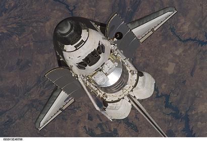
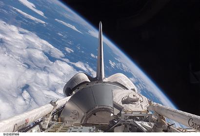
The Multi-Purpose Logistics Module (MPLM) is a pressurized module that is used on Space Shuttle missions to transfer cargo to and from the International Space Station (ISS).


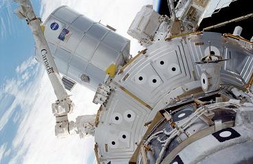
A typical MPLM mission starts in the cargo bay of a Space Shuttle. The MPLM is carried to the ISS and berthed to one of the docking modules by the Canadian robotic arm. The supplies are offloaded and then finished experiments and waste are loaded on to the module. At the end of the mission, the MPLM is moved to the Space Shuttle cargo bay and returned to Earth.


The Italian Space Agency (ASI) provides the modules to NASA. Three MPLMs have been built and delivered to NASA thus far. NASA owns the MPLMs and ASI receives research time on ISS in exchange. The MPLMs were named after great figures in Italian history: Leonardo, Raffaello, and Donatello. However, some of the mission badges display the ninja turtles instead.


The construction of the first MPLM – Leonardo – began in April 1996. Leonardo was delivered to NASA in August 1998. Raffaello and Donatello followed in August 1999 and February 2001, respectively. Each MPLM can make 25 return trips to space.


Credits: NASA


The MPLM is 6.4 meters long and 4.6 meters in diameter. The module weighs 4.5 tons and it can deliver up to 10 tons to the ISS. The design of the module resembles the payload module that is part of the ATV. In addition, ATV has a service module that offers autonomy. Obviously, ATV was the direct beneficiary of the knowledge gained during the design and operational phases of the MPLM.


There is room for sixteen standard payload racks (International Standard Payload Racks – ISPR) in the MPLM. Even if it is not used to carry a human crew, MPLM has its own life-support system. Furthermore, it has a 3 KW internal power supply.


Credits: NASA


The current Space Shuttle mission – STS 126 – has delivered the MPLM Leonardo to the ISS. Leonardo is on its fifth spaceflight and hauled over 14,000 pounds of supplies and equipment to ISS.


Part (a small part) of the payload was turkey, candied yams, stuffing, and dessert for a Thanksgiving meal at the station.


A special piece of equipment, the GLACIER, was also delivered to the station. GLACIER stands for General Laboratory Active Cryogenic ISS Experiment Refrigerator. GLACIER is a double locker cryogenic freezer that will be used for transporting and preserving science experiments. The payload also included a galley for the Destiny laboratory, an advanced Resistive Exercise Device (aRED), and two new crew quarter racks for the expanded station crew.


Credits: NASA


There are two more MPLM missions scheduled before the Space Shuttle retires. STS-128 will carry Leonardo in July 2009, and Raffaello will be docked to ISS during the STS-131 mission in February 2010.


  • Facebook
  • Google
  • Slashdot
  • Reddit
  • Live
  • TwitThis
November 18, 2008

Carnival of Space #79

Posted by


Credits: ESA – S. Corvaja 2007


The Carnival of Space #79 is hosted by Nicole at One Astronomer’s Noise.


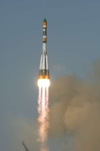
There are a lot of interesting stories to be found in this edition of the carnival: garden shed-sized nuclear reactors, alien abductions, space and politics, the Phoenix Mars Lander, and Kuiper Belt Objects, among other topics. OrbitalHub submitted a post about the Russian Soyuz launch vehicle.


  • Facebook
  • Google
  • Slashdot
  • Reddit
  • Live
  • TwitThis
November 18, 2008

PHOENIX

Posted by


Credits: NASA


In 2002, an instrument on the Mars Odyssey spacecraft detected hydrogen under the Martian surface. This was regarded as clear evidence that there is subsurface water ice on Mars.


In 2003, NASA decided to revive a mission that was cancelled in 2001 due to the fact that a previous mission, the Mars Polar Lander, was lost in 1999. The revived mission was named Phoenix.


A Lander that could reach out and touch the ice was needed. The half-built spacecraft for the previously cancelled mission already had in place a 7.7-foot robotic arm that could do the trick.


A JPL team reviewed the data from the failed mission in 1999 and corrected the mistakes made. Every system used in the previous design was taken apart, tested, and examined. The suspected culprits were the retrorockets used during landing. More than a dozen issues that could have caused a failure of the new planned mission were found and fixed.
 

Credits: NASA / JPL


The Phoenix mission inherited a capable spacecraft partially built for the Mars Surveyor Program 2001. As we mentioned, the lessons learned from the Mars Polar Lander helped improve the existing systems. As for any other space mission, the conditions in which the spacecraft operates dictate the design.


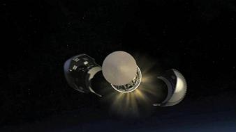
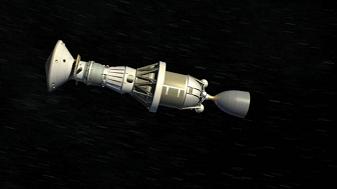
In the case of the Phoenix mission, the following phases were considered: the launch, the cruise, the atmospheric entry, the touchdown, and the surface operations phase. The launch induces tremendous load forces and vibrations. The 10-month cruise to Mars exposes the spacecraft to the vacuum of space, solar radiation, and possible impacts with micrometeorites. During the atmospheric entry, the spacecraft is heated to thousands of degrees due to aero braking, and has to withstand tremendous deceleration during the parachute deployment. The extremely cold temperatures of the Martian arctic and the dust storms must be considered during the surface operations phase.
 

Credits: NASA / JPL


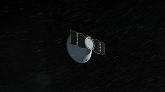
Several instruments are mounted on the Lander: the robotic arm (RA), the robotic arm camera (RAC), the thermal and evolved gas analyzer (TEGA), the Mars descent imager (MARDI), the meteorological station (MET), the surface stereo imager (SSI), and the microscopy, electrochemistry, and conductivity analyzer (MECA).


The RA was built by the Jet Propulsion Laboratory and was designed to perform the scouting operations on Mars, such as digging trenches and scooping the soil and water ice samples. RA delivered the samples to the TEGA and the MECA. RA is 2.35 meters long, it has an elbow joint in the middle, and it is capable of digging trenches 0.5 meters deep in the Martian soil.


The University of Arizona and the Max Planck Institute in Germany built the RAC. The camera is attached to the RA, just above the scoop placed at the end of the arm. RAC provided close-up, full-color images.
 

Credits: NASA / JPL


TEGA was developed by the University of Arizona and University of Texas, Dallas. TEGA used eight tiny ovens to analyze eight unique ice and soil samples. By employing a process called scanning calorimetry, and by using a mass spectrometer to analyze the gas obtained in the furnaces as the temperature raised to 1000 degrees Celsius, TEGA determined the ratio of various isotopes of hydrogen, oxygen, carbon, and nitrogen.


MARDI was built by Malin Space Science Systems. From what I could gather, the MARDI was not used by the Lander due to some integration issues.


The Canadian Space Agency (YAY Canada!) was responsible for the overall development of the meteorological station (MET). Two companies from Ontario, MD Robotics and Optech Inc., provided the instruments for the station.


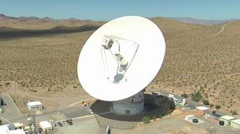
The SSI served as the eyes of the Phoenix mission. SSI provided high-resolution, stereo, panoramic images of the Martian arctic. An extended mast holds the SSI, so the images were recorded from two meters above the ground.
 

Credits: NASA / JPL


MECA was built by the Jet Propulsion Laboratory. The instrument was used to characterize the soil by dissolving small amounts of soil in water. MECA determined the pH, the mineral composition, as well as the concentration of dissolved oxygen and carbon dioxide in the soil samples that were collected.


We would like to highlight some of the important moments during the mission:


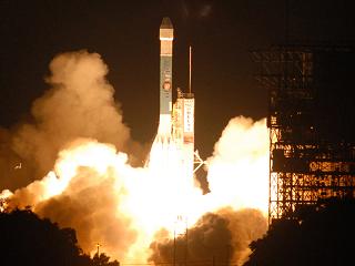
August 4, 2007 – Delta II rocket launch from Cape Canaveral. The three-stage Delta II rocket with nine solid rocket boosters lifted off from Cape Canaveral, carrying the Phoenix spacecraft on the first leg of its journey to Mars.
 

Credits: NASA / JPL -Caltech / University of Arizona


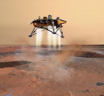
May 25, 2008 – Phoenix Mars Lander touchdown. The Phoenix entered the Martian atmosphere at 13,000 mph. It took 7 minutes for the Lander to slow down with the aid of a parachute and to land using its retrorockets. The mission team did not have to wait long before discovering ice because the blasts from the retrorockets had blown away the topsoil during landing and revealed ice patches under the lander.


November 2, 2008 – Last signal received from the Lander. On this date, communication was established for the last time with Phoenix. Due to the latitude of the landing site, not enough sunlight is available and the solar arrays are unable to collect the power necessary to charge the batteries that operate the instruments mounted on the Lander. At the landing site, the weather conditions are worsening.


November 10, 2008 – Mission declared completed. NASA declares that the Mars Phoenix Lander has completed a successful mission on the Red Planet. Phoenix Mars Lander has ceased communications after being operational for more than five months (the designed operational life of the mission was 90 days).


November 13, 2008 – Mission Honored. NASA’s Phoenix Mars Lander was awarded Best of What’s New Grand Award in the aviation and space category by Popular Science magazine.
 

Credits: NASA / JPL


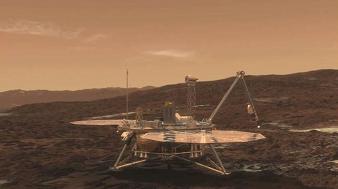
The Mars Phoenix Lander made significant contributions to the study of the Red Planet. Phoenix verified the presence of water ice under the Martian surface, and it returned thousands of pictures from Mars. Phoenix also found small concentrations of salts that could be nutrients for life, it discovered perchlorate salt, and calcium carbonate, which is a marker of effects of liquid water.


Phoenix provided a mission long weather record, with data on temperature, pressure, humidity, and wind, as well as observations on snow, haze, clouds, frost, and whirlwinds.


Principal Investigator Peter H. Smith of the University of Arizona led the Phoenix mission. The project management was done at NASA’s Jet Propulsion Laboratory and the development at Lockheed Martin Space Systems in Denver. Other contributors were the Canadian Space Agency, the University of Neuchatel (Switzerland), the University of Copenhagen (Denmark), the Max Planck Institute (Germany), and the Finnish Meteorological Institute.


For more information about the Phoenix mission, check out the NASA Phoenix Mars Lander Page.


  • Facebook
  • Google
  • Slashdot
  • Reddit
  • Live
  • TwitThis


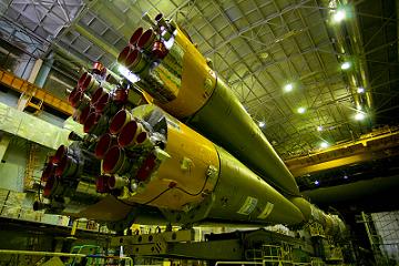
Credits: ESA – S. Corvaja 2007


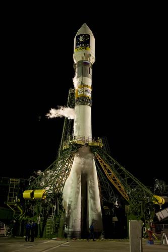
CNES and ESA signed the development contract to build the launch facilities for Soyuz at the Guiana Space Centre on July 19, 2005. The Soyuz launcher will give Europe medium-lift capability and will complete the range of launchers operated by Arianespace, which includes the Ariane 5 heavy-lift launcher and the Vega small launcher.


The Soyuz launchers that will liftoff from Kourou have a number of improvements: an updated digital flight control system, an increased-performance third stage, and the larger Soyuz ST payload fairing.


The launcher has a length of 46.2 meters, a diameter of 10.3 meters, and a liftoff mass of 308 tons. Due to the position of the launch site, close to the equator, the payload capacity of the launcher has increased significantly: 3,150 kg to a geostationary orbit, and 4,900 kg to a sun-synchronous orbit, with a circular altitude of 820 km.


Soyuz is a reliable, four-stage launch vehicle, which has been in production since 1957 and has accounted for more than 1,700 missions to date.


The first stage is composed of the four boosters that are assembled around the central core of the launcher. The RD-107A engines installed on the boosters use liquid oxygen and kerosene as propellant combination. Each engine has four combustion chambers and four nozzles. One aerofin and two movable vernier thrusters per engine are used for the three-axis flight control.


Credits: ESA – S. Corvaja 2008


The second stage consists of the central core surrounded by the boosters. It uses the same propellant combination for powering the RD-108A engine with four combustion chambers and nozzles.


Four vernier thrusters are used for three-axis flight control, after the boosters of the first stage are jettisoned during flight.


The engines of the first two stages are ignited 20 seconds before liftoff. The reason for this is that the launch procedures include monitoring the engine health parameters just before liftoff, while the engines are operating at an intermediate level of thrust. This reminds me of the SpaceX Falcon 1 booster launch procedures. SpaceX engineers perform a similar monitoring procedure for the Merlin engine just before the Falcon 1 liftoff.


The third stage utilizes a RD-0124 engine, also powered by liquid oxygen and kerosene. The liquid oxygen and kerosene tanks are pressurized using helium stored in vessels located in the liquid oxygen tank. The avionics module of the launcher is carried by this stage. The new flight control system improves the accuracy and the control capability for the launcher, as additional flight control authority is needed for the enlarged payload fairing.


Credits: ESA – S. Corvaja 2008


The upper stage of the Soyuz launcher is called Fregat. Fregat is an autonomous and flexible upper stage with its own guidance, navigation, control, tracking, and telemetry systems. It was designed to operate as an orbital vehicle, and it extends the launch capabilities of the Soyuz launcher to medium-Earth orbits, Sun-synchronous orbits, geostationary transfer orbits, and Earth escape trajectories.


The Fregat stage can be restarted up to 20 times in flight, it can provide three-axis stabilization, and perform a spin-up of the spacecraft payload. Fregat uses a bi-propellant propulsion system: UDMH (unsymmetrical dimethylhydrazine) and NTO (nitrogen tetroxide).


The payload fairing is the most visible change to the Soyuz launcher. The new Soyuz fairing has a diameter of 4.11 meters and a length of 11.4 meters. The fairing is based on the configuration used for Ariane 4 vehicles.


The construction of the Soyuz launch base in French Guiana started in early 2007. At the groundbreaking ceremony on February 26, 2007, a number of European space industry officials were present: Jean-Jacques Dordain – ESA Director General, Yannick d’Escatha – President of CNES, Jean-Yves Le Gall – Director General of Arianespace, and Anatoly Perminov – Head of Roscosmos.


In 2007, Arianespace ordered four Soyuz launchers for the early launch missions that are scheduled for the second half of 2009. A contract was also signed in September 2008 for 10 more Soyuz launch vehicles.


The Soyuz launch missions that are scheduled for 2009 signal the beginning of a new chapter in ESA-Russian relations. Stay tuned for more information about the Soyuz launches from French Guiana!


  • Facebook
  • Google
  • Slashdot
  • Reddit
  • Live
  • TwitThis
November 7, 2008

Carnival of Space #78

Posted by


Credits: ESA – J. Huart


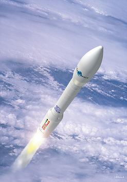
The Carnival of Space #78 is hosted by Mike Simonsen at SIMOSTRONOMY. OrbitalHub has submitted a post about Vega – the new European small launcher.


  • Facebook
  • Google
  • Slashdot
  • Reddit
  • Live
  • TwitThis


Credits: ESA


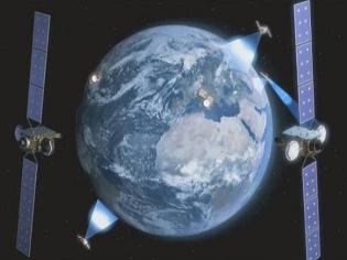
ESA is developing a new satellite communication system that will revolutionize the way Europe gets its information from space. This new communication system is called EDRSS – the European Data Relay Satellite System.


EDRSS will use geostationary satellites to communicate with both ground stations and satellites that are operating in low Earth orbits.


EDRSS will allow low Earth orbit satellites to deliver data continuously, instead of storing it on board and sending it to Earth while flying over a ground station. EDRSS will consist of a network of satellites that will communicate between themselves as well as with the ground stations. This new infrastructure will increase the speed at which ground stations receive data from satellites, thereby improving global communication, navigation, and Earth observation.


EDRSS will serve as a communication infrastructure and it will improve many key services: monitoring earthquakes, forest fires, floods, and aircraft navigation, just to name a few.


You can watch an ESA video cast for more details.


  • Facebook
  • Google
  • Slashdot
  • Reddit
  • Live
  • TwitThis