OrbitalHub

The place where space exploration, science, and engineering meet

Domain is for sale. $50,000,000.00 USD. Direct any inquiries to contact@orbitalhub.com.

Archive for 2008

October 2, 2008

Jules Verne Ends the Space Journey

Posted by


We covered the ATV Jules Verne mission in a previous post (Jules Verne close to the End of its Space Journey) and mentioned that the typical ATV mission ends with a destructive re-entry above the Pacific Ocean. We come back with this post to present the conclusion of the ATV mission.


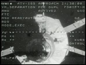
Credits: NASA


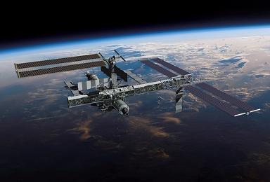
The ATV separated from the International Space Station (ISS) on September 5, 2008, filled with more than 2 tonnes of waste. The ATV undocked from the aft port of the Zvezda Service Module and it was placed in a parking orbit for three weeks. While being parked, a series of tests of the guidance and control systems were performed.

By carrying out re-phasing maneuvers, the ATV positioned itself to a predefined position behind and underneath the ISS. In this way, the crews from the ISS and from two specially equipped observation planes in the skies of the South Pacific were able to view and to record the re-entry.


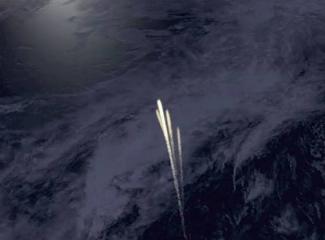
Credits: NASA


The re-entry was initially modeled on computer in order to anticipate the trajectory and the location of the area where the breakout fragments of the spacecraft will fall. The observations helped determine if the re-entry matched the computer modeling.


As planned, the first ATV mission concluded on September 29, 2008, when two engine burns de-orbited the spacecraft. ESA scheduled the re-entry on this date because the lighting conditions were appropriate for an imagery experiment and the breakup happened at approximately 75 km above the waters of the Pacific Ocean. The remaining fragments fell into the Pacific some 12 minutes later.


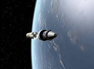
Credits: ESA


This first mission proved the logistical value of the ATV. The delivery of 6 tonnes of cargo to the ISS, the automatic rendezvous and docking capabilities, the attitude control maneuvers performed, they all show how far the European space capabilities have developed.


ESA engineers are already working on the next two ATV spacecrafts. The next ATV mission is scheduled for 2010 and there are many proposals to adapt the ATV to other types of missions.


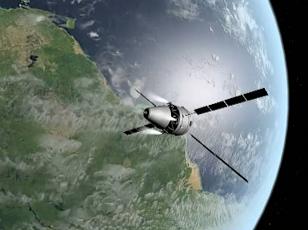
Credits: ESA


One important variation of the typical ATV mission is the Large Cargo Return (LCR). The LCR configuration will consist of a large cargo capsule capable of bringing back on Earth hundreds of kilograms of cargo and valuable experiment results. LCR would be able to dock to the US side of the ISS that has larger docking ports and would make possible the transfer of complete payload racks.


The video showing the destructive re-entry of Jules Verne is available on the ESA website.


  • Facebook
  • Google
  • Slashdot
  • Reddit
  • Live
  • TwitThis
October 1, 2008

ESA to Study the Birth of the Universe

Posted by


Some of the most important questions asked in modern science are: how did the Universe begin, how did it evolve to its present state, and how will it continue to evolve in the future? To ask these questions, the remnant radiation that filled the Universe immediately after the Big Bang must be analyzed. This remnant radiation is known as the Cosmic Microwave Background (CMB).
 

Credits: ESA


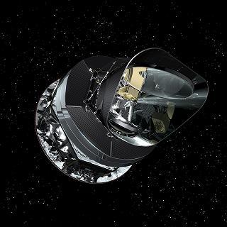
ESA plans to answer these questions with Planck: the first European mission to study the birth of the Universe. The Planck Mission will collect CMB radiation measurements using highly sensitive sensors that are operating at very low temperatures. The measurements will be used to map the smallest variations of the CMB detected to date.


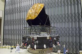
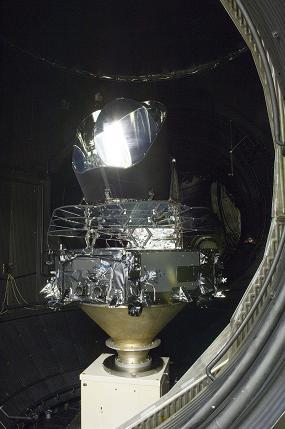
The Planck spacecraft will weigh around 1,900 kg at launch. It is 4.2 m high and has a maximum diameter of 4.2 m. There are two modules that comprise the spacecraft: a service module and the payload module.


The service module contains the systems for power generation, attitude control, data handling and communication, and the warm components of the scientific payload. The payload module contains the telescope, the optical bench, the detectors, and the cooling system (which is of critical importance, as we shall see).


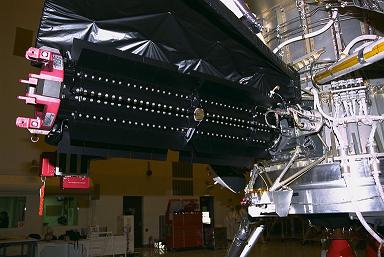
The telescope is an important onboard component. The Planck telescope is a Gregorian telescope with an off-axis parabolic primary mirror 1.75 x 1.5 meters in size. A secondary mirror focuses the incoming microwave radiation on two sets of highly sensitive detectors: the Low Frequency Instrument (LFI) and the High Frequency Instrument (HFI). The Gregorian design offers two key advantages: it is compact and it does not block the optical path.
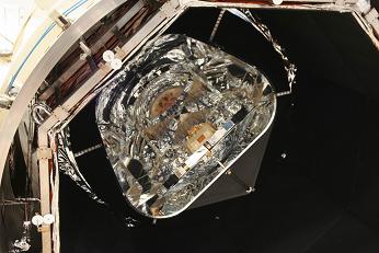
 

Credits: ESA/Thales


The LFI will be operating at –253 degrees Celsius. The array of twenty-two tuned radio receivers that comprise LFI will produce high-sensitivity, multi-frequency measurements of the microwave sky in the frequency range of 27 GHz to 77 GHz.


The HFI has to be cooled to –272.9 degrees Celsius in order to operate (one tenth of one degree above the absolute zero!). HFI’s fifty-two bolometric detectors will produce high-sensitivity, multi-frequency measurements of the diffuse sky radiation in the frequency range of 84 GHz to 1 THz.


A baffle surrounds the telescope and instruments. The baffle prevents light from the Sun and the Moon from altering the measurements. A complex system of refrigerators is used onboard the spacecraft in order to achieve the temperatures needed for nominal operation. The detectors have to work at temperatures close to the absolute zero, otherwise their own emissions can alter the measurements.


The two instruments will be used to measure the small variations of the CMB across the sky. By combining the measurements, a full sky map of unprecedented precision will be produced. The map will help astronomers decide which theories on the birth and the evolution of the Universe are correct. Questions like ‘what is the age of the Universe?’ or ‘what is the nature of the dark-matter?’ will be answered.


The mission was initially designed as COBRAS/SAMBA (Cosmic Background Radiation Anisotropy Satellite and Satellite for Measurement of Background Anisotropies) because it grew out of two mission proposals that had similar objectives. When the mission was approved in 1996, it was also renamed as Planck in honor of the German scientist Max Planck (1858 – 1947). Max Planck was awarded the Nobel Prize for Physics in 1918.
 

Credits: ESA


The mission is a collaborative effort. The Planck spacecraft was designed and built by a consortium led by Alcatel Alenia Space (Cannes, France). The telescope mirrors are manufactured by EADS Astrium (Friedrichshafen, Germany). The Low Frequency Instrument (LFI) was designed and built by a consortium led by the Instituto di Astrofisica Spaziale e Fisica Cosmica (IASF) in Bologna, Italy. The High Frequency Instrument (HFI) was designed and built by a consortium led by the Institut d’Astrophysique Spatiale (CNRS) in Orsay, France.


The Planck Mission has two predecessors: the Cosmic Background Explorer (COBE) and the Wilkinson Microwave Anisotropy Probe (WMAP).
 

Credits: ESA


The Planck spacecraft will be launched in early 2009 from Kourou, French Guiana. An Ariane 5 booster will place the spacecraft in a trajectory towards the L2 point. The L2 point stands for Second Lagrangian Point and it is located around 1.5 million kilometers away from Earth in a direction diametrically opposite the Sun. It will be a dual launch configuration, as the Herschel spacecraft will be launched together with Planck.


Between four to six months after the launch, Planck will reach its final position. It will take six more months before Planck will be declared operational.


Planck will perform scientific measurements for fifteen months, allowing two complete sky surveys. The spacecraft will be operational as along as there are resources for the cooling systems onboard.


For more details on the ESA’s Planck Mission you can visit the mission’s home page on the ESA website.


  • Facebook
  • Google
  • Slashdot
  • Reddit
  • Live
  • TwitThis
September 29, 2008

Falcon 1 Takes Flight

Posted by


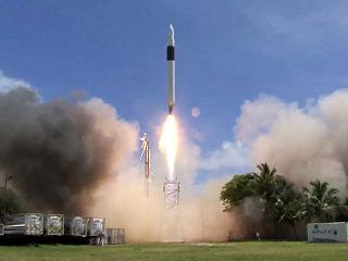
After six years of tremendous effort and more than $100 million USD spent, SpaceX made a successful launch of Falcon 1. Falcon 1 is the first booster built by a private company to ever reach the Earth’s orbit. This is the fourth Falcon 1 mission.


Credits: SpaceX


The booster lifted off yesterday from the testing site on Omelek Island in the Kwajalein Atoll located in the central Pacific some 2,500 miles southwest of Hawaii.


The previous three missions were not successful, but SpaceX managed to remove all the stumbling blocks out of the way. In less than two months from the previous attempt, on August 2nd 2008, SpaceX had another booster ready for launch.


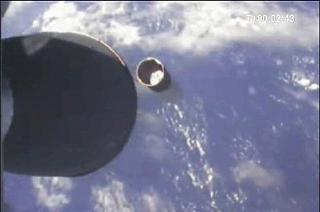
The payload carried by the Flight 4 mission is a mass simulator that weighs around 165 kg. The payload did not separate but remained attached to the second stage as it orbits the Earth.


Falcon 1 is a two-stage booster. It uses liquid oxygen and rocket grade kerosene as fuel. The booster is 21.3 meters long and 1.7 meters in diameter. It weighs 27, 670 kg when ready to launch. The first stage of the booster is powered by a Merlin 1C engine and the upper stage is powered by a Kestrel engine.


The Merlin 1C engine is a turbo pump fed engine, while the smaller Kestrel engine uses tank pressure to inject the fuel into its combustion chamber. In order to simplify the design, the Merlin engine uses the high-pressure kerosene to cool the combustion chamber and the nozzle. In addition, the engine uses the high-pressure kerosene for the hydraulic actuators, thereby eliminating the need for a separate hydraulic power system.


Credits: SpaceX


Falcon 1 is the first in a family of launch vehicles that SpaceX will build and operate. NASA awarded Commercial Orbital Transportation Services (COTS) funding to SpaceX to demonstrate delivery and return of cargo and potentially a human crew to the International Space Station (ISS). In order to achieve these goals, SpaceX is developing a bigger booster, Falcon 9, and a cargo and crew capsule, Dragon.


SpaceX holds a unique position in the launch vehicle market, being able to take over the delivery of supplies and human crews to the ISS, after the Space Shuttle’s retirement in 2010. For more information about SpaceX and its fleet of launch vehicles, check out their website.


  • Facebook
  • Google
  • Slashdot
  • Reddit
  • Live
  • TwitThis
September 28, 2008

Power Generation Onboard Spacecrafts (III)

Posted by


In a previous post we presented the most common solution for power generation onboard unmanned spacecrafts (solar cells and secondary batteries) and mentioned some of the manned spacecrafts that employ this solution.


Credits: NASA


However, solar cells, in combination with secondary batteries, are not usable for missions beyond the asteroid belt, because there the sun’s energy becomes too diffuse. As deep space missions were designed, a new power source was required. The radioisotope thermoelectric generators, also known as RTGs, met the requirements for this kind of mission. RTGs are proven, compact, and reliable power sources that can produce up to several kilowatts of power and operate under severe conditions for many years.


RTGs convert the heat generated by a decay of radioactive fuel into electricity. There are two major components that RTGs consist of: the heat source that contains the radioactive material and a set of solid-state thermocouples that convert the heat energy to electricity. The principle that RTGs rely on is not a new discovery. In 1821, Thomas Johann Seebeck discovered the effect that bears his name and that allows us to convert heat directly into electricity using a simple and robust device. An electrical current is generated when two dissimilar electrically conductive materials are connected in a closed circuit and their junctions are kept at different temperatures. The heat generated by the radioactive decay is used to heat the hot junction of the thermocouple, and exposure to the cold outer space is used to maintain the temperature of the cold junction.


Credits: NASA


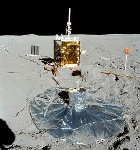
Over the years, RTGs have been used safely and reliably on many missions. Among these missions: some of the Apollo flights to the moon, the Pioneer spacecrafts, the Viking landers, the Voyager missions, the Galileo mission, the Ulysses mission, and the Cassini-Huygens mission. The present conversion efficiency achieved by the thermocouples is around 10%, and research continues in order to improve it. Because of the internal resistance and other losses, the overall RTG efficiency is typically 6-7%, which means that the amount of waste heat for every unit of electrical energy produced is quite large.


Even if the radioisotopes used present a loss in energy with time, the half-life of the radioisotopes is not a major life-limiting factor of current RTGs. Major life-limiting factors include the degradation of the thermoelectric elements and the breakdown of insulators because of temperature and radiation.


The radiation emissions from RTGs can damage the electronics onboard spacecrafts. This is why it is necessary to mount the units on booms at some distance from the body of the spacecraft or, at least, provide shielding of some sort in the on orbit configuration. One important thing to mention is that in the launch configuration, when the RTG boom cannot be deployed, the radiation exposure cannot exceed the inherent radiation tolerance of the onboard electronics.


There are two more solutions spacecraft engineers employ to generate power onboard spacecrafts and we will present them in our next post. Please come back later to read our conclusion to the series.


  • Facebook
  • Google
  • Slashdot
  • Reddit
  • Live
  • TwitThis
September 27, 2008

24/7 Live Space Talk Now Available

Posted by


The conversations between the astronauts onboard the International Space Station and the flight controllers at the Mission Control are now being broadcast live on NASA’s website. The communications are available to the public 24 hours a day, seven days a week.


Credits: NASA


In order to open the audio stream, go to the NASA web page, click on the NASA TV(live) tab at the center of the page, and then click on the Shuttle and Station Audio link.


You will have to be patient because most of the time the broadcast is silent. I managed to catch 15 minutes of conversation this morning! The conversation was between NASA’s astronaut Gregory Chamitoff and the Mission Control in Houston.


Just to remind you, Gregory is also getting ready for the chess matches organized by NASA and the U.S. Chess Federation beginning on Monday, September 29th.


  • Facebook
  • Google
  • Slashdot
  • Reddit
  • Live
  • TwitThis
September 26, 2008

Carnival of Space #72

Posted by


Carnival of Space #72 is hosted by Jennifer Ouellette at Twisted Physics. Check out the great articles from around the space blogosphere this week!


  • Facebook
  • Google
  • Slashdot
  • Reddit
  • Live
  • TwitThis