OrbitalHub

The place where space exploration, science, and engineering meet

Domain is for sale. $50,000,000.00 USD. Direct any inquiries to contact@orbitalhub.com.

Archive for the Robotic Exploration category

December 15, 2008

MRO Completed First Phase of Its Mission

Posted by


Credits: NASA/JPL

The Mars Reconnaissance Orbiter (MRO) has completed the first phase of its science mission. During this phase, the orbiter returned seventy-three terabits of science data to Earth, which is more than all earlier Mars missions combined. The next phase of the MRO mission will take two years.


The list of scientific discoveries and observations made by MRO is stunning. We know now that Mars has a long history of climate change and that water was present in liquid form on its surface for hundreds of millions of years.


Signatures of a variety of watery environments have been observed, so future missions will be aware of locations that might reveal evidence of past life on Mars, if it ever existed.


MRO has imaged nearly forty percent of the Martian surface at such a high resolution that house-sized objects can be seen in detail. MRO has also conducted a mineral survey of the planet, covering sixty percent of its surface. Global weather maps were assembled using the data returned by MRO, and profiles of the subsurface and the polar caps have been put together using the radar mounted on MRO.


Credits: NASA/KSC

“These observations are now at the level of detail necessary to test hypotheses about when and where water has changed Mars and where future missions will be most productive as they search for habitable regions on Mars,” said Richard Zurek, Mars Reconnaissance Orbiter project scientist.


The images returned by MRO have been used by the Phoenix team to change the spacecraft’s landing site, and will help the NASA scientists select landing sites for future missions, like the Mars Science Laboratory (MSL).


Another role played by MRO was to relay commands to and to return data from the Phoenix lander during the five months the lander was operational on the Martian surface. MRO shared this task with the Mars Odyssey Orbiter.


MRO lifted off on August 12, 2005, from launch Complex 41 at Cape Canaveral Air Force Station. The cruise phase of the mission lasted seven months, the spacecraft reaching Mars orbit on March 10, 2006, after traveling on an outbound arc intercept trajectory.


MRO entered the final low orbit suited for science-data collection on November 2006, after slowing down in the Martian atmosphere by using aerobraking for five months. The first phase of the mission consisted in gathering information about Mars, and the remaining time left of its operational life will be dedicated mainly to using the spacecraft as a communication relay.


Credits: NASA/KSC

The declared goals of the MRO mission are: to determine whether life ever arose on Mars, to characterize the climate of Mars, to characterize the geology of Mars, and to prepare for human exploration.


The launcher of choice for the MRO mission was the Atlas V-401 launch vehicle, the smallest of the Atlas V family. This was the first launch of an Atlas V on an interplanetary mission.


The Atlas V-401 is a two-stage launch vehicle that does not use solid rocket boosters. The Atlas V-401 is fifty-seven meters tall and has a total mass at liftoff of 333,000 kg. Out of this, about 305,000 kg is fuel. In order to reach Mars orbit, MRO was accelerated to 11 km per second.


The first stage of the Atlas V, the Common Core Booster, is powered by liquid oxygen and RP-1. For the MRO mission, the first stage used a RD-180 engine. The RD-180 engine has an interesting story. It is a Russian-developed rocket engine, derived from the RD-170 used for the Zenit rockets.


Credits: NASA/JPL/KSC/Lockheed Martin Space Systems

Rights to use the RD-180 engine were acquired by General Dynamics Space Systems Division (later purchased by Lockheed Martin) in the early 1990s. The engine is co-produced by Pratt & Whitney and all production to date has been in Russia. According to Pratt & Whitney, RD-180 delivers a ten percent performance increase over current operational U.S. booster engines.


The stage weighs approximately 305,000 kg at launch and it provides about four million Newton of thrust for four minutes.


The upper stage of the Atlas V is the Centaur Upper Stage Booster. The Centaur is powered by liquid oxygen and liquid hydrogen. In the case of the MRO mission, it provided the remaining energy necessary to send the spacecraft to Mars.


The payload fairing used for the MRO mission was four meters in diameter. The role of the payload fairing was to protect the spacecraft from the weather on the ground as well as from the dynamic pressure during the atmospheric phase of the launch.


Lockheed Martin Commercial Launch Services developed the Atlas V as part of the US Air Force Evolved Expendable Launch Vehicle (EELV) program.


There are six science instruments, three engineering instruments, and two science-facility experiments carried by the MRO. The low orbit on which MRO is operating allowed the observation of the surface, atmosphere, and subsurface of Mars in unprecedented detail.


The science instruments are the HiRISE camera (High Resolution Imaging Science Experiment), the CTX camera (Context Camera), the MARCI camera (Mars Color Imager), the CRISM spectrometer (Compact Reconnaissance Imaging Spectrometer for Mars), the MCS radiometer (Mars Climate Sounder), and the SHARAD radar (SHAllow RADar).


Credits: HiRISE/MRO/LPL/NASA


The HiRISE camera provided the highest-resolution images from orbit to date, while the SHARAD can probe the subsurface using radar waves in the 15-25 MHz frequency band (these waves can penetrate the Martian crust up to one kilometer).


The engineering instruments assist the spacecraft navigation and communication. The Electra UHF Communications and Navigation Package is used as a communication relay between the Earth and landed crafts on Mars. The Optical Navigation Camera serves as a high-precision camera to guide incoming spacecrafts as they approach Mars. The Ka-band Telecommunications Experiment Package demonstrated the use of the Ka-band for power effective communications.


The science facility experiments are the Gravity Field Investigation Package, used for mapping the gravity field of Mars, and the Atmospheric Structure Investigation Accelerometers, which helped scientists understand the structure of the Martian atmosphere.


For more details on the MRO scientific payload, you can check out the dedicated page on the MRO mission web site.


The MRO was built by Lockheed Martin for NASA’s Jet Propulsion Laboratory in California. Fully loaded, the spacecraft had a mass of almost two tons. The spacecraft carried 1,149 kg of propellant for trajectory correction maneuvers and for the burns needed for the Mars capture.


Credits: NASA/JPL


The main bus of the spacecraft presents two massive solar arrays that can generate 2,000 W of power. On top, the high-gain antenna is the main means of communication with both Earth and other spacecrafts. The SHARAD antenna is the long pole behind the bus.


Other visible features are the HiRISE camera, the Electra telecommunications package, and the Context Imager (CTX).


You can visit the home page of the MRO mission on the NASA web site.


  • Facebook
  • Google
  • Slashdot
  • Reddit
  • Live
  • TwitThis
November 18, 2008

PHOENIX

Posted by


Credits: NASA


In 2002, an instrument on the Mars Odyssey spacecraft detected hydrogen under the Martian surface. This was regarded as clear evidence that there is subsurface water ice on Mars.


In 2003, NASA decided to revive a mission that was cancelled in 2001 due to the fact that a previous mission, the Mars Polar Lander, was lost in 1999. The revived mission was named Phoenix.


A Lander that could reach out and touch the ice was needed. The half-built spacecraft for the previously cancelled mission already had in place a 7.7-foot robotic arm that could do the trick.


A JPL team reviewed the data from the failed mission in 1999 and corrected the mistakes made. Every system used in the previous design was taken apart, tested, and examined. The suspected culprits were the retrorockets used during landing. More than a dozen issues that could have caused a failure of the new planned mission were found and fixed.


Credits: NASA / JPL


The Phoenix mission inherited a capable spacecraft partially built for the Mars Surveyor Program 2001. As we mentioned, the lessons learned from the Mars Polar Lander helped improve the existing systems. As for any other space mission, the conditions in which the spacecraft operates dictate the design.


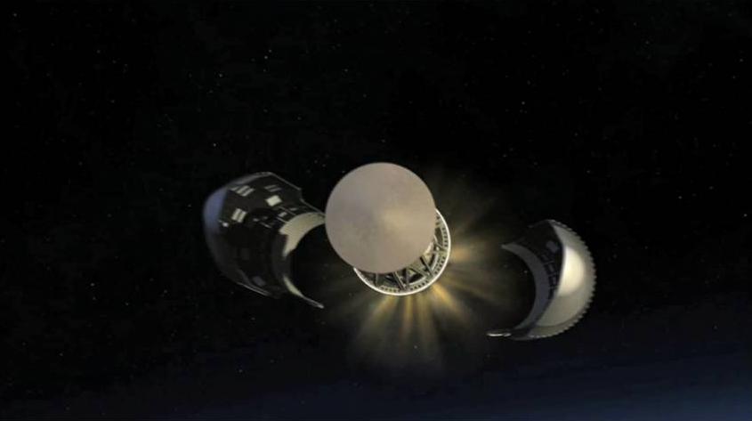
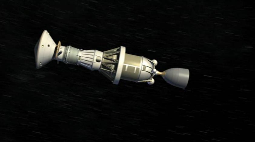
In the case of the Phoenix mission, the following phases were considered: the launch, the cruise, the atmospheric entry, the touchdown, and the surface operations phase. The launch induces tremendous load forces and vibrations. The 10-month cruise to Mars exposes the spacecraft to the vacuum of space, solar radiation, and possible impacts with micrometeorites. During the atmospheric entry, the spacecraft is heated to thousands of degrees due to aero braking, and has to withstand tremendous deceleration during the parachute deployment. The extremely cold temperatures of the Martian arctic and the dust storms must be considered during the surface operations phase.


Credits: NASA / JPL


Several instruments are mounted on the Lander: the robotic arm (RA), the robotic arm camera (RAC), the thermal and evolved gas analyzer (TEGA), the Mars descent imager (MARDI), the meteorological station (MET), the surface stereo imager (SSI), and the microscopy, electrochemistry, and conductivity analyzer (MECA).


The RA was built by the Jet Propulsion Laboratory and was designed to perform the scouting operations on Mars, such as digging trenches and scooping the soil and water ice samples. RA delivered the samples to the TEGA and the MECA. RA is 2.35 meters long, it has an elbow joint in the middle, and it is capable of digging trenches 0.5 meters deep in the Martian soil.


The University of Arizona and the Max Planck Institute in Germany built the RAC. The camera is attached to the RA, just above the scoop placed at the end of the arm. RAC provided close-up, full-color images.


Credits: NASA / JPL


TEGA was developed by the University of Arizona and University of Texas, Dallas. TEGA used eight tiny ovens to analyze eight unique ice and soil samples. By employing a process called scanning calorimetry, and by using a mass spectrometer to analyze the gas obtained in the furnaces as the temperature raised to 1000 degrees Celsius, TEGA determined the ratio of various isotopes of hydrogen, oxygen, carbon, and nitrogen.


MARDI was built by Malin Space Science Systems. From what I could gather, the MARDI was not used by the Lander due to some integration issues.


The Canadian Space Agency (YAY Canada!) was responsible for the overall development of the meteorological station (MET). Two companies from Ontario, MD Robotics and Optech Inc., provided the instruments for the station.


The SSI served as the eyes of the Phoenix mission. SSI provided high-resolution, stereo, panoramic images of the Martian arctic. An extended mast holds the SSI, so the images were recorded from two meters above the ground.


Credits: NASA / JPL


MECA was built by the Jet Propulsion Laboratory. The instrument was used to characterize the soil by dissolving small amounts of soil in water. MECA determined the pH, the mineral composition, as well as the concentration of dissolved oxygen and carbon dioxide in the soil samples that were collected.


We would like to highlight some of the important moments during the mission:


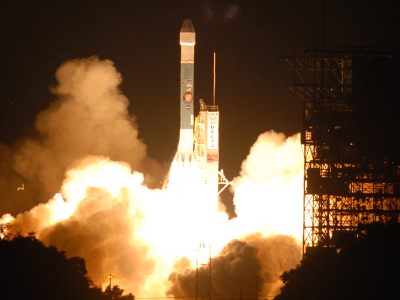
August 4, 2007 – Delta II rocket launch from Cape Canaveral. The three-stage Delta II rocket with nine solid rocket boosters lifted off from Cape Canaveral, carrying the Phoenix spacecraft on the first leg of its journey to Mars.


Credits: NASA / JPL -Caltech / University of Arizona


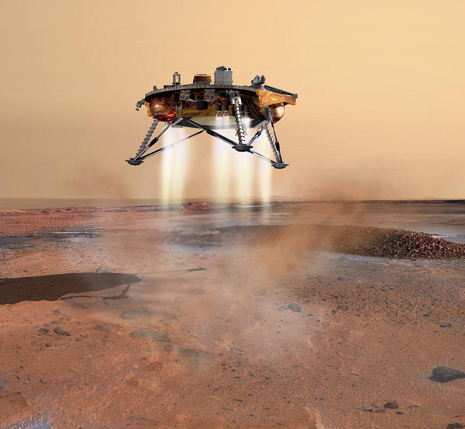
May 25, 2008 – Phoenix Mars Lander touchdown. The Phoenix entered the Martian atmosphere at 13,000 mph. It took 7 minutes for the Lander to slow down with the aid of a parachute and to land using its retrorockets. The mission team did not have to wait long before discovering ice because the blasts from the retrorockets had blown away the topsoil during landing and revealed ice patches under the lander.


November 2, 2008 – Last signal received from the Lander. On this date, communication was established for the last time with Phoenix. Due to the latitude of the landing site, not enough sunlight is available and the solar arrays are unable to collect the power necessary to charge the batteries that operate the instruments mounted on the Lander. At the landing site, the weather conditions are worsening.


November 10, 2008 – Mission declared completed. NASA declares that the Mars Phoenix Lander has completed a successful mission on the Red Planet. Phoenix Mars Lander has ceased communications after being operational for more than five months (the designed operational life of the mission was 90 days).


November 13, 2008 – Mission Honored. NASA’s Phoenix Mars Lander was awarded Best of What’s New Grand Award in the aviation and space category by Popular Science magazine.


Credits: NASA / JPL


The Mars Phoenix Lander made significant contributions to the study of the Red Planet. Phoenix verified the presence of water ice under the Martian surface, and it returned thousands of pictures from Mars. Phoenix also found small concentrations of salts that could be nutrients for life, it discovered perchlorate salt, and calcium carbonate, which is a marker of effects of liquid water.


Phoenix provided a mission long weather record, with data on temperature, pressure, humidity, and wind, as well as observations on snow, haze, clouds, frost, and whirlwinds.


Principal Investigator Peter H. Smith of the University of Arizona led the Phoenix mission. The project management was done at NASA’s Jet Propulsion Laboratory and the development at Lockheed Martin Space Systems in Denver. Other contributors were the Canadian Space Agency, the University of Neuchatel (Switzerland), the University of Copenhagen (Denmark), the Max Planck Institute (Germany), and the Finnish Meteorological Institute.


For more information about the Phoenix mission, check out the NASA Phoenix Mars Lander Page.


  • Facebook
  • Google
  • Slashdot
  • Reddit
  • Live
  • TwitThis
October 29, 2008

Herschel, Planck’s Big Brother

Posted by


Credits: ESA/AOES Medialab


In a previous post, we presented the Planck spacecraft. We would like to dedicate this post to Planck’s big brother, Herschel. Why b(r)other? Because Planck and Herschel will be launched into space by the same Ariane 5 launcher and they will share the fairing section during the launch phase of the mission. Why big? Well, because Herschel is a larger spacecraft than Planck… actually Herschel is the largest space telescope ever built.


Just to have an idea about the size of the infrared telescope onboard the Herschel spacecraft, the primary mirror has a diameter of 3.5 m and a mass of only 350 kg. In comparison, the mirror of the Hubble space telescope has a diameter of 2.4 m and a mass of 1.5 tons. Obviously, a great deal of effort has been put into minimizing the mass of the telescope, an advance made possible by present-day technology.


The infrared telescope will become operational four months after its launch and will have a nominal mission lifetime of three years. The objectives that ESA set for the Herschel Space Observatory are ambitious: the study of the galaxies in the early universe, the investigation of the creation of stars, the observation of the chemical composition of the atmosphere and surfaces of comets, planets and satellites, as well as examining the molecular chemistry of the universe.


Like Planck, Herschel will observe the sky from the second Lagrangean Point (L2) of the Sun-Earth system. The instruments onboard Herschel will collect long-wavelength infrared radiation. Herschel will be the only space observatory to cover the spectral range from the far infrared to sub-millimeter, which is the reason why the initial name of the space observatory was Far Infrared and Sub-millimeter Telescope (FIRST).


Credits: ESA


The Herschel spacecraft will have 3.3 tons at launch, with a length of 7.5 m and a cross section of 4×4 m. The spacecraft comprises of two modules: the service module and the payload module. While the service module contains the systems for power conditioning, attitude control, data handling and communications, and the warm parts of the scientific instruments, the payload module contains the telescope, the optical bench, the cold parts of the scientific instruments and the cooling system. A sunshield protects the telescope and the cryostat from solar radiation. The sunshield also carries solar cells for power generation.


In order to make accurate observations of the infrared spectrum, parts of the scientific instruments onboard have to be cooled to temperatures close to absolute zero. Two thousand liters of liquid helium will be used for primary cooling during the mission. In addition, each detector onboard is equipped with additional cooling systems.


Credits: ESA/Guarniero


Herschel will not be the first infrared telescope launched into space. There are three predecessors that we would like to mention here: IRAS, the US-Dutch-British satellite launched in 1983, ISO – launched by ESA in 1995, and the NASA’s Spitzer Space Telescope – launched in 2003. However, these three infrared space telescopes were operated on Earth orbits. As we mentioned, Herschel will operate in the L2 point, away from any interference that would affect the scientific instruments onboard. Operating in the L2 point will also help with regard to thermal stability because the spacecraft will not move in and out of eclipse regions.


The launch date is set for early 2009. The journey to the final operational position will take around four months. The European Space Operations Control Center (ESOC) in Darmstadt will coordinate the mission.


  • Facebook
  • Google
  • Slashdot
  • Reddit
  • Live
  • TwitThis
October 18, 2008

NASA’s IBEX Ready For Launch

Posted by


Credits: NASA GSFC


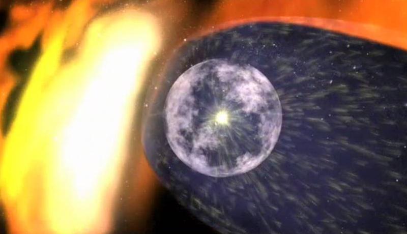
The solar wind generated by our Sun carves out a protective bubble around the solar system, called the heliosphere. The interstellar medium, consisting of the gas and the dust found between the galaxies, interacts with the solar wind and defines the actual boundary, which is called the termination shock.


NASA has designed a mission to map the boundary of the solar system. The mission is called IBEX (Interstellar Boundary Explorer) and it is ready to launch. The data collected by IBEX will allow scientists to understand the interaction between our Sun and the galaxy for the first time. Understanding this interaction will help us protect future astronauts from the danger of galactic cosmic rays.


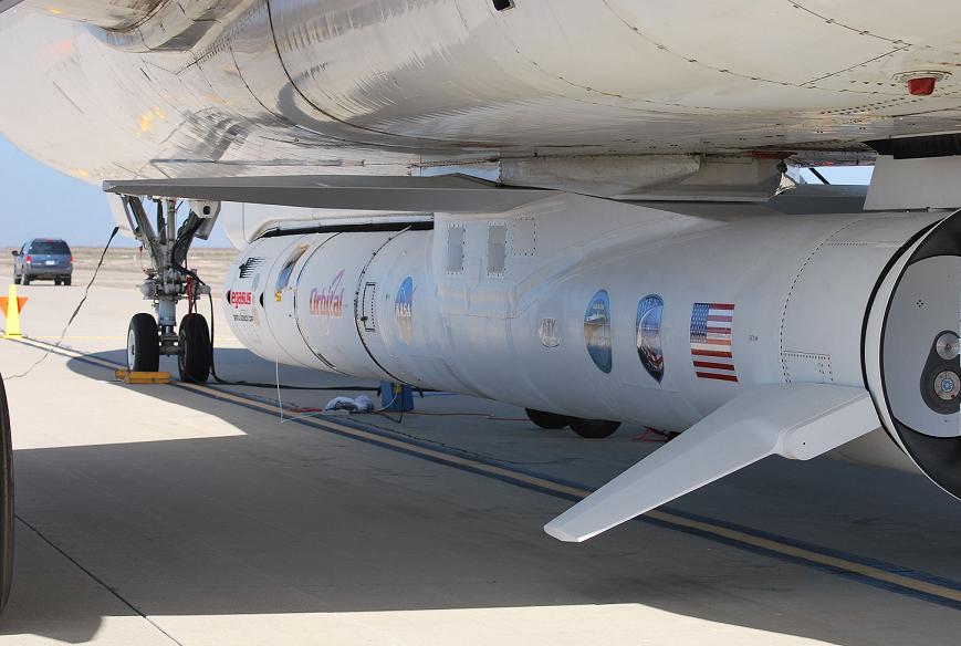
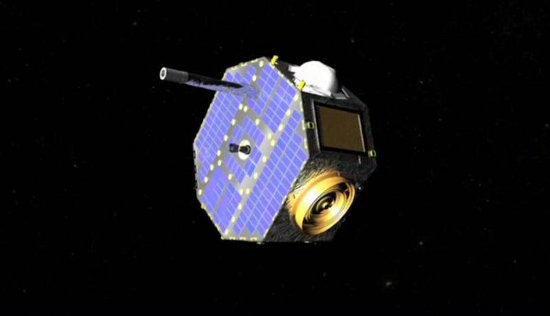
In January 2005, the Orbital Science Corporation was selected to develop, build, and launch a small spacecraft for NASA’s IBEX mission. The IBEX spacecraft is based on an already existing bus: the MicroStar satellite. IBEX will be launched by a Pegasus XL rocket, which will be dropped from an aircraft flying over the Pacific Ocean.


Credits: NASA GSFC


Pegasus began its commercial career in April 1990, and since then it has launched more than 80 satellites into space.


Pegasus is a three-stage launching system used to deploy small satellites weighing up to 1,000 pounds into Low Earth Orbit (LEO). An aircraft carries Pegasus to an altitude of 40,000 feet.


The rocket is released and free-falls before igniting its engines. It takes roughly ten minutes for Pegasus to deliver a satellite into orbit.


Pegasus will place IBEX into a 130 mile altitude orbit. An extra solid-fueled rocket will boost the spacecraft from the LEO. IBEX’s final orbit will be a highly elliptical orbit with the perigee at an altitude of 7,000 km and the apogee at 236,000 km. IBEX has to operate in this orbit because any interference from the Earth’s magnetosphere would make it impossible to take accurate measurements with the scientific instruments onboard.


Credits: NASA GSFC


IBEX has a mass of only 83.33 lbs (roughly 38 kg) and is described by NASA as being the size of a bus tire. The instruments onboard IBEX will collect particles called energetic neutral atoms (ENAs). The ENAs are radiated from the termination shock region. The ENA hits recorded by the instruments onboard IBEX will be used to create a map of this region.


The mission is scheduled to launch tomorrow, October 19th, 2008. The spacecraft will be operational for 24 months. You can find out more about the IBEX spacecraft on NASA’s IBEX mission web page.


  • Facebook
  • Google
  • Slashdot
  • Reddit
  • Live
  • TwitThis
October 15, 2008

Scouting the Moon (III)

Posted by


Credits: NASA


In the previous two posts in this series, we presented NASA’s Lunar Reconnaissance Orbiter (LRO) and the Chandrayaan-1 mission, which was designed and developed by ISRO. These two missions are typical lunar scouting missions: the spacecraft with onboard remote-sensing instruments will orbit the Moon, collect scientific data, and relay it back to Earth.


NASA will launch another lunar scouting spacecraft on the same Atlas V rocket with LRO: the Lunar Crater Observation and Sensing Satellite (LCROSS). This mission is not a typical scouting mission and we will see why in this post.


In 1999, a precursor of LRO and LCROSS called the Lunar Prospector detected traces of concentrated hydrogen at the lunar poles. As a result, the LCROSS mission’s main goal is to confirm the presence or absence of water in a permanently shadowed crater near a lunar polar region. At the present time, landing a probe on the lunar surface and performing excavations or drilling would be very expensive. A less expensive solution for the LCROSS mission is to use a kinetic impactor to excavate a crater on the surface of the Moon.


Credits: NASA


After the launch, LRO will separate from LCROSS, and continue on a solo journey to the Moon. LCROSS will remain attached to the Centaur upper stage of the Atlas V launch system.


While LRO will follow a trajectory that will place it in a polar lunar orbit, LCROSS will execute a flyby of the Moon, and use an elongated Earth orbit to position itself on an impact trajectory. During this time, the LCROSS mission team will perform instrument calibration and corrections for the impact trajectory. The target of the impact will be the lunar south pole.


Seven minutes before the impact, LCROSS will separate from Centaur. The Centaur will be used as a kinetic impactor. Having a mass of approximately 2,200 kg, on impact, it will excavate a crater 20 meters wide and 3 meters deep. According to NASA scientists, more than 250 tons of lunar material will be propelled into space.


Credits: NASA


LCROSS will then fly through the debris of the previous impact. The instruments onboard LCROSS will collect scientific data and the spacecraft will relay it back to Earth. LCROSS will end its mission four minutes after the Centaur impact by creating its own impact crater on the lunar surface. The last S in LCROSS should stand for Smasher instead of Satellite considering the final act of the mission!


The scientific instruments onboard LCROSS cover a wide spectrum: two near-infrared spectrometers, a visible light spectrometer, two mid-infrared cameras, two near-infrared cameras, a visible camera, and a visible radiometer. The instruments can detect traces of organics, hydrocarbons, hydrated minerals, water ice, and water vapor. More details about the LCROSS scientific payload can be found on LCROSS mission page.


I wonder to what extent the debris caused by the impact of Centaur and LCROSS will interfere with the scientific instruments onboard LRO and Chandrayaan-1. Both LRO and Chandrayaan-1 will be orbiting the Moon on polar orbits at that time.


  • Facebook
  • Google
  • Slashdot
  • Reddit
  • Live
  • TwitThis
October 8, 2008

Scouting the Moon (II)

Posted by


We presented in a previous post the Lunar Reconnaissance Orbiter (LRO) mission. The goals of the LRO mission are to map the lunar resources and to create a detailed 3D map of the lunar surface in preparation for future NASA missions to the Moon. However, NASA is not the only space agency that has high hopes regarding the exploration of the Moon. The Indian Space Research Organization (ISRO) is another agency heavily involved in space activities.


Credits: ISRO


Interest in undertaking a lunar scientific mission was sparked at a meeting of the Indian Academy of Sciences in 1999. One year later, the Astronautical Society of India made a recommendation supporting the idea.


The ISRO formed a National Lunar Mission Task Force that involved leading Indian scientists. The Task Force provided an assessment on the feasibility of such a mission. The mission, called Chandrayaan-1, was approved in November 2003 for an estimated cost of $83 million USD.


The Chandrayaan-1 spacecraft is a 1.5 meter cube with a weight mass of approximately 523 kg. The spacecraft bus is based on an already developed meteorological satellite. Chandrayaan-1 will carry a 30 kg probe that will be released to penetrate the lunar surface. The power for the onboard systems is generated by a solar panel. The 750 watts generated by the solar panel will be stored by the rechargeable batteries onboard the spacecraft. Maneuvering in the lunar orbit is done using a bipropellant propulsion system.


Credits: ISRO


The scientific payload contains a diverse collection of instruments. The instruments were designed and developed by ISRO, ESA, NASA, and the Bulgarian Space Agency.


There are two instruments that will map the surface of the Moon: the Terrain Mapping Camera (TMC) will produce a 5 meter resolution map of the surface, and the Lunar Laser Ranging Instrument (LLRI) will scan the lunar surface and determine the surface topography.


The X-ray spectrometer onboard the spacecraft has three components: the Imaging X-ray Spectrometer (CIXS), the High Energy X-ray/gamma ray spectrometer (HEX), and the Solar X-ray Monitor (SXM). The X-ray spectrometer will measure the concentration of certain elements on the lunar surface as well as monitor the solar flux in order to normalize the results of the measurements taken.


The mineralogical configuration of the surface will be mapped by four instruments: the Hyper Spectral Imager (HySI), the Sub-keV Atom Reflecting Analyzer (SARA), the Moon Mineralogy Mapper (M3), and the Near-Infrared Spectrometer (SIR-2).


The Radiation Dose Monitor (RADOM-7) will record the radiation levels in the lunar orbit.


Credits: ISRO


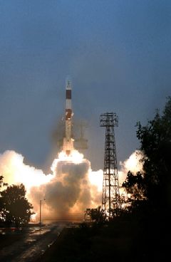
ISRO has two operational launch vehicles: the Polar Satellite Launch Vehicle (PSLV) and the Geosynchronous Satellite Launch Vehicle (GSLV). For Chandrayaan-1, ISRO has chosen to use PSLV as a launch vehicle. The PSLV developmental flights were completed in 1996 and the rocket has had 12 successful missions since then. PSLV is 44.43 meters tall and has a weight of 294 tonnes at launch. It can inject a payload of 1,000 kg – 1,200 kg into a polar orbit.


The launch of the Chandrayaan-1 mission is scheduled for the end of October 2008. The PSLV rocket will take off from the Satish Dhawan Space Center in Sriharikota on the southeast coast of India. The transfer to the lunar orbit will take approximately five days and after additional maneuvers the spacecraft will reach its final polar orbit, 100 km above the surface. The spacecraft will be operational for two years.


The Chandrayaan-1 mission opens the door to future lunar missions. ISRO has already committed to a second Chandrayaan mission that will land a rover on the surface of the Moon. The rover will perform a number of experiments on the lunar surface and the results will be relayed to Earth by the Chandrayaan-2 orbiter.


We will come back with more details about the Chandrayaan-1 mission as the events unfold. Please stay tuned on the OrbitalHub frequency.


  • Facebook
  • Google
  • Slashdot
  • Reddit
  • Live
  • TwitThis