OrbitalHub

The place where space exploration, science, and engineering meet

Domain is for sale. $50,000,000.00 USD. Direct any inquiries to contact@orbitalhub.com.


Credits: NASA


Software is a key component of present-day aerospace systems. Increased reliability is required from operating systems that host critical software applications.


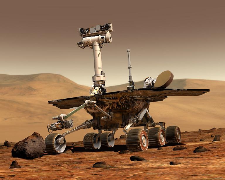
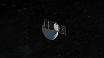
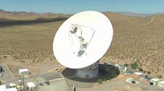
Wind River’s VxWorks is a real-time operating system that is widely used in the aerospace industry. Missions using VxWorks include the Mars Reconnaissance Orbiter, the Phoenix Mars Lander, the Deep Impact space probe, Spirit and Opportunity Mars Exploration Rovers, and Stardust.


Mike Deliman, Senior Engineering Specialist at Wind River Systems, answered a few questions related to the new VxWorks MILS Platform 2.0.


DJ: What is VxWorks MILS Platform 2.0?
Mike Deliman: VxWorks MILS Platform 2.0 is a platform for creating systems that are evaluatable to high levels of the Common Criteria / Evaluated Assurance Level scale. VxWorks MILS 2.0 separation kernel is currently under evaluation by NIAP labs to an EAL 6+ level. The VxWorks MILS 2.0 Platform contains a separation kernel and technology to allow you to create multi-partitioned software systems where each partition can be evaluated to handle multiple independent levels of security (MILS) or to handle multiple levels of security (MLS). The long-and-short of it is similar to a VxWorks 653 flight OS, you can use a VxWorks MILS 2 platform to design a single platform that is capable of replacing multiple legacy systems. In other words, like a VxWorks 653 flight system, you can create a single modern system to replace multiple legacy systems, reducing Space, Weight and Power (SWaP) requirements.


DJ: What is a separation kernel and how did the concept make its way into software development for the aerospace industry?
M.D.: Separation Kernels allow you to take a single modern high-powered CPU and use it to replace several legacy systems. There are many examples of separation kernels and paradigms for their use. ARINC 653 defines a time and memory-space partitioning paradigm, services, and an API that must be provided (the Application Executive, or APEX). We have a platform – VxWorks 653 – that implements the ARINC 653 APEX separation and API. Separation Technologies are becoming quite popular, many are called “Hypervisors”. There are many Hypervisors out in cyberspace, the “Type 1” Hypervisors can all be thought of as forms of separation kernels. The Aerospace industry is a prime target for separation technologies because of the need to reduce the “SWaP” factors.


DJ: How does the VxWorks MILS separation kernel improve the reliability of aerospace applications?
M.D.: The VxWorks MILS separation kernel could be used to allow a single satellite to fulfill multiple missions. For instance, there may be a number of sensors and experiments on board, some for civilian / educational interests, some for NASA, some for research entities, perhaps some for the USAF. A MILS kernel could be used to collect, encode, and steer data safely, providing assurance that the data will not be mixed until it is in a state deemed “safe” for mixing. A satellite running a MILS separation kernel to handle such data wrangling could combine and satisfy multiple mission masters. If I were to be asked to design such a system, I would most likely recommend a flight computer separate from the science computer. Even if the science and flight SW were to share a single CPU, the separation technology would help ensure that no problems on any science application could affect any of the other science applications or any flight applications. In this way the flight system would be protected from anomalous events in the science packages, and the overall system would benefit from improved reliability.


DJ: John Rushby introduced the concept of separation kernel in order to provide multilevel secure operation on general-purpose multi-user systems. Do software applications developed for the aerospace industry (and I have in mind software running on micro-controllers) have the level of complexity that would require a separation kernel?
M.D.: Concentrating on the micro-controller aspect, no, most single (federated) systems running one micro-controller (or even several) do not even need a 32-bit processor dedicated to their operation. However, with a proper separation kernel and time-sliced architecture, you could use one modern high-speed 32-bit CPU to control and monitor a large number of smaller systems, and ensure any faults occurring on those control-and-monitor loops are contained. And as noted above, in a system used to satisfy requirements of multiple masters (agencies), MILS-style data separation may be the only way to keep satellite weight within limits and provide the information assurance the agencies require.


DJ: What features make the VxWorks operating system reliable and secure?
M.D.: Focusing on the VxWorks family of operating systems and the VxWorks OS API, VxWorks has been used in millions of devices over more than two decades of service, in applications as simple as MP3 players and as complex as autonomous space exploring robots, and as life-critical as telerobotic surgeons. There is no way a software company could anticipate the wide range of use that our customers have dreamed up and implemented. The VxWorks family of OSes share a common ancestry of code and all can benefit from bugs discovered and fixed in any of the family line.
 
Focusing on the VxWorks MILS platform, the separation kernel was designed expressly in compliance with the SKPP (the Protection Profile for separation kernels), with a focus on controlling embedded applications that require some degree of real-time control.


DJ: What are the features that make VxWorks a real-time operating system?
M.D.: Determinism is king in the real-time world. The ability to react to events in the real world with a high degree of determinism is what gives VxWorks its hard real-time responsiveness. This hard-determinism is carried over into all of the VxWorks family line, including our separation kernels and VxWorks SMP.


DJ: What toolchain is shipped with VxWorks? What programming languages are supported by the toolchain?
M.D.: Depending on the VxWorks package, one or more toolchains may be supplied and supported. For the most part, various versions of the Wind River Complier (formerly “Diab”), and various versions of the Gnu tools are supplied / supported with VxWorks. For the VxWorks MILS 2 platform we use a couple of versions of the GNU tool chains, specially modified for the parts they are used to build.


DJ: What hardware is targeted by the platform? Is an actual board necessary for development of applications or is an emulated target environment available for software engineers?
M.D.: Specifically, chips we are targeting include the following:
– Freescale 8641D (CW VPX6-165)
– Freescale 8548 (Wind River SBC8548)
– Intel Core 2 Duo (Supermicro C2SBC-Q)
– Freescale P2020, P1011, P4080 (future)
– Intel Atom, Nehalem (future)
We currently support Simics as the only simulation environment available for the VxWorks MILS platform.


Wind River Systems was founded in Berkeley, California in 1981. Intel bought Wind River Systems for a reported $884 million in July 2009. VxWorks real-time operating system is one of the Wind River flagship products.


  • Facebook
  • Google
  • Slashdot
  • Reddit
  • Live
  • TwitThis
04-17-09

Delta II

Posted by


Credits: NASA/MSFC


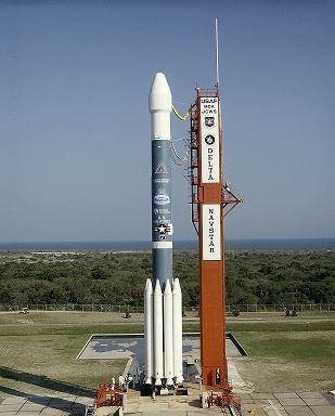
Delta II is a space launch system operated by United Launch Alliance (ULA), which was initially built by McDonnell Douglas, and by Boeing Integrated Defense Systems after McDonnell Douglas merged with Boeing in 1997.


As any other early space launch system, it evolved from a ballistic missile. In the 1960s, the Thor intermediate-range ballistic missile was modified to become the Delta launch vehicle. In 1981, after being operated for 24 years, Delta production was halted due to a change in U.S. space policy. However, in 1986, after the Challenger accident, it was decided that the Space Shuttle fleet would not carry commercial payloads anymore, paving the way for the return of the Delta launch vehicle. Delta II had its maiden flight on February 14, 1989.


Delta II launch vehicle is 38.2 to 39 m long, with a diameter of 2.44 m, and a mass that can range from 151,700 to 231,870 kg, depending on configuration. Delta II can be configured with two or three stages.


Delta II can inject a payload having a mass of 2,700 to 6,100 kg in low Earth orbit (LEO). Payloads deployed to Geosynchronous Transfer Orbit (GTO) can have a mass from 900 to 2,170 kg.


The first stage, Thor/Delta XLT-C, is powered by one Pratt & Whitney Rocketdyne RS-27A liquid fuel engine. The RS-27A engine is fueled by RP-1 and liquid oxygen. The RS-27A engine provides around 1,000 kN of thrust.


Credits: NASA


The solid boosters are used to increase the thrust of the launch vehicle. The first solid boosters used by Delta II 6000 series were Castor 4A motors. The 7000 and 7000 Heavy series use GEM 40 and GEM 46 solid motors respectively. The increase in thrust from Castor 4A to GEM 46 is substantial, from 480 kN to 630 kN.


Stage two, Delta K, is powered by a hypergolic restartable Aerojet AJ10-118K engine that can provide 43 kN. The AJ10-118K can fire more than once in order to insert the payload into LEO. The engine uses dinitrogen tetroxide as oxidizer and aerozine 50 (which is a mix of hydrazine and unsymmetrical dimethylhydrazine) as fuel. Besides having hard to pronounce names, the oxidizer and the fuel are very toxic and corrosive. The second stage contains the flight control system, which is a combined inertial system and guidance system.


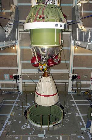
The third stage, if present in the configuration, is a Payload Assist Module (PAM). This stage is powered by an ATK-Thiokol motor, which provides the velocity change needed for missions beyond Earth orbit. The stage has no active guidance control and it is spin-stabilized.


The de-spin mechanism used to slow the spin of the spacecraft after the burn and before the stage separation is a yo-yo de-spin mechanism. This mechanism consists of two cables with weights on the ends. The weights are released and the angular momentum transferred from the stage reduces the spin to a value that can be controlled by the attitude control system of the spacecraft.


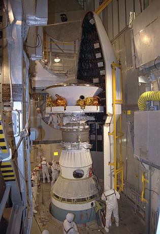
Delta II can launch single, dual, or multiple payloads during the same mission. There are three fairing sizes available: composite 3-meter diameter, aluminum 2.9-meter diameter, and stretched composite 3-meter diameter.


Credits: NASA


Delta II is assembled on the launch pad. After hoisting the first stage into position, the solid boosters are hoisted and mated with the first stage. The second stage is then hoisted atop the first stage.


Delta II launch vehicles have a four-digit naming system. The first digit can be either 6 or 7, designating the 6000 or 7000 series. The second digit indicates the number of solid boosters used for the mission. Delta II can have three, four, or nine solid boosters strapped to the first stage. The third digit denotes the engine type used for the second stage. This digit is two for 6000 and 7000 series Delta II, which indicates the Aerojet A10 engine. The last digit designates the type of the third stage. Zero means that no third stage is used, whereas five indicates a third stage powered by a Star 48B solid motor, and 6 marks a third stage powered by a Star 37FM motor. A Delta II 7426 has 4 solid boosters and a third stage powered by a Star 37FM motor.


Delta II proved to be a very reliable Expendable Launch Vehicle (ELV). Some NASA missions that used Delta II as launch vehicle include: Mars Global Surveyor, Mars Pathfinder, Mars Exploration Rovers (MER-A Spirit and MER-B Opportunity), Mars Phoenix Lander, Dawn, STEREO, and Kepler.


After long years of service, Delta II is getting close to retirement. The final mission for Delta II is currently scheduled for 2011.


You can find more information about the Delta launch vehicles on the Delta web page on Boeing’s web site.


  • Facebook
  • Google
  • Slashdot
  • Reddit
  • Live
  • TwitThis


Credits: NASA/JPL

The Mars Reconnaissance Orbiter (MRO) has completed the first phase of its science mission. During this phase, the orbiter returned seventy-three terabits of science data to Earth, which is more than all earlier Mars missions combined. The next phase of the MRO mission will take two years.


The list of scientific discoveries and observations made by MRO is stunning. We know now that Mars has a long history of climate change and that water was present in liquid form on its surface for hundreds of millions of years.


Signatures of a variety of watery environments have been observed, so future missions will be aware of locations that might reveal evidence of past life on Mars, if it ever existed.


MRO has imaged nearly forty percent of the Martian surface at such a high resolution that house-sized objects can be seen in detail. MRO has also conducted a mineral survey of the planet, covering sixty percent of its surface. Global weather maps were assembled using the data returned by MRO, and profiles of the subsurface and the polar caps have been put together using the radar mounted on MRO.


Credits: NASA/KSC

“These observations are now at the level of detail necessary to test hypotheses about when and where water has changed Mars and where future missions will be most productive as they search for habitable regions on Mars,” said Richard Zurek, Mars Reconnaissance Orbiter project scientist.


The images returned by MRO have been used by the Phoenix team to change the spacecraft’s landing site, and will help the NASA scientists select landing sites for future missions, like the Mars Science Laboratory (MSL).


Another role played by MRO was to relay commands to and to return data from the Phoenix lander during the five months the lander was operational on the Martian surface. MRO shared this task with the Mars Odyssey Orbiter.


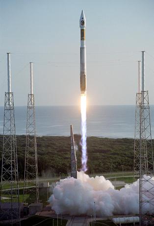
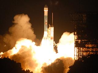
MRO lifted off on August 12, 2005, from launch Complex 41 at Cape Canaveral Air Force Station. The cruise phase of the mission lasted seven months, the spacecraft reaching Mars orbit on March 10, 2006, after traveling on an outbound arc intercept trajectory.


MRO entered the final low orbit suited for science-data collection on November 2006, after slowing down in the Martian atmosphere by using aerobraking for five months. The first phase of the mission consisted in gathering information about Mars, and the remaining time left of its operational life will be dedicated mainly to using the spacecraft as a communication relay.


Credits: NASA/KSC

The declared goals of the MRO mission are: to determine whether life ever arose on Mars, to characterize the climate of Mars, to characterize the geology of Mars, and to prepare for human exploration.


The launcher of choice for the MRO mission was the Atlas V-401 launch vehicle, the smallest of the Atlas V family. This was the first launch of an Atlas V on an interplanetary mission.


The Atlas V-401 is a two-stage launch vehicle that does not use solid rocket boosters. The Atlas V-401 is fifty-seven meters tall and has a total mass at liftoff of 333,000 kg. Out of this, about 305,000 kg is fuel. In order to reach Mars orbit, MRO was accelerated to 11 km per second.


The first stage of the Atlas V, the Common Core Booster, is powered by liquid oxygen and RP-1. For the MRO mission, the first stage used a RD-180 engine. The RD-180 engine has an interesting story. It is a Russian-developed rocket engine, derived from the RD-170 used for the Zenit rockets.


Credits: NASA/JPL/KSC/Lockheed Martin Space Systems

Rights to use the RD-180 engine were acquired by General Dynamics Space Systems Division (later purchased by Lockheed Martin) in the early 1990s. The engine is co-produced by Pratt & Whitney and all production to date has been in Russia. According to Pratt & Whitney, RD-180 delivers a ten percent performance increase over current operational U.S. booster engines.


The stage weighs approximately 305,000 kg at launch and it provides about four million Newton of thrust for four minutes.


The upper stage of the Atlas V is the Centaur Upper Stage Booster. The Centaur is powered by liquid oxygen and liquid hydrogen. In the case of the MRO mission, it provided the remaining energy necessary to send the spacecraft to Mars.


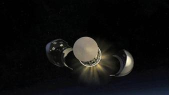
The payload fairing used for the MRO mission was four meters in diameter. The role of the payload fairing was to protect the spacecraft from the weather on the ground as well as from the dynamic pressure during the atmospheric phase of the launch.


Lockheed Martin Commercial Launch Services developed the Atlas V as part of the US Air Force Evolved Expendable Launch Vehicle (EELV) program.


There are six science instruments, three engineering instruments, and two science-facility experiments carried by the MRO. The low orbit on which MRO is operating allowed the observation of the surface, atmosphere, and subsurface of Mars in unprecedented detail.


The science instruments are the HiRISE camera (High Resolution Imaging Science Experiment), the CTX camera (Context Camera), the MARCI camera (Mars Color Imager), the CRISM spectrometer (Compact Reconnaissance Imaging Spectrometer for Mars), the MCS radiometer (Mars Climate Sounder), and the SHARAD radar (SHAllow RADar).


Credits: HiRISE/MRO/LPL/NASA


The HiRISE camera provided the highest-resolution images from orbit to date, while the SHARAD can probe the subsurface using radar waves in the 15-25 MHz frequency band (these waves can penetrate the Martian crust up to one kilometer).


The engineering instruments assist the spacecraft navigation and communication. The Electra UHF Communications and Navigation Package is used as a communication relay between the Earth and landed crafts on Mars. The Optical Navigation Camera serves as a high-precision camera to guide incoming spacecrafts as they approach Mars. The Ka-band Telecommunications Experiment Package demonstrated the use of the Ka-band for power effective communications.


The science facility experiments are the Gravity Field Investigation Package, used for mapping the gravity field of Mars, and the Atmospheric Structure Investigation Accelerometers, which helped scientists understand the structure of the Martian atmosphere.


For more details on the MRO scientific payload, you can check out the dedicated page on the MRO mission web site.


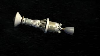
The MRO was built by Lockheed Martin for NASA’s Jet Propulsion Laboratory in California. Fully loaded, the spacecraft had a mass of almost two tons. The spacecraft carried 1,149 kg of propellant for trajectory correction maneuvers and for the burns needed for the Mars capture.


Credits: NASA/JPL


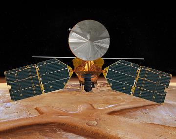
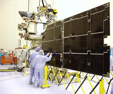
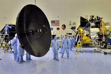
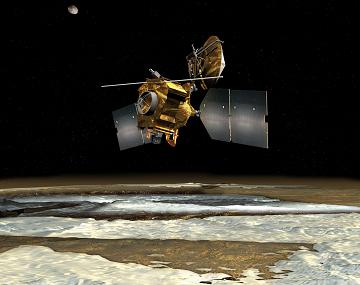
The main bus of the spacecraft presents two massive solar arrays that can generate 2,000 W of power. On top, the high-gain antenna is the main means of communication with both Earth and other spacecrafts. The SHARAD antenna is the long pole behind the bus.


Other visible features are the HiRISE camera, the Electra telecommunications package, and the Context Imager (CTX).


You can visit the home page of the MRO mission on the NASA web site.


  • Facebook
  • Google
  • Slashdot
  • Reddit
  • Live
  • TwitThis
11-18-08

PHOENIX

Posted by


Credits: NASA


In 2002, an instrument on the Mars Odyssey spacecraft detected hydrogen under the Martian surface. This was regarded as clear evidence that there is subsurface water ice on Mars.


In 2003, NASA decided to revive a mission that was cancelled in 2001 due to the fact that a previous mission, the Mars Polar Lander, was lost in 1999. The revived mission was named Phoenix.


A Lander that could reach out and touch the ice was needed. The half-built spacecraft for the previously cancelled mission already had in place a 7.7-foot robotic arm that could do the trick.


A JPL team reviewed the data from the failed mission in 1999 and corrected the mistakes made. Every system used in the previous design was taken apart, tested, and examined. The suspected culprits were the retrorockets used during landing. More than a dozen issues that could have caused a failure of the new planned mission were found and fixed.


Credits: NASA / JPL


The Phoenix mission inherited a capable spacecraft partially built for the Mars Surveyor Program 2001. As we mentioned, the lessons learned from the Mars Polar Lander helped improve the existing systems. As for any other space mission, the conditions in which the spacecraft operates dictate the design.


In the case of the Phoenix mission, the following phases were considered: the launch, the cruise, the atmospheric entry, the touchdown, and the surface operations phase. The launch induces tremendous load forces and vibrations. The 10-month cruise to Mars exposes the spacecraft to the vacuum of space, solar radiation, and possible impacts with micrometeorites. During the atmospheric entry, the spacecraft is heated to thousands of degrees due to aero braking, and has to withstand tremendous deceleration during the parachute deployment. The extremely cold temperatures of the Martian arctic and the dust storms must be considered during the surface operations phase.


Credits: NASA / JPL


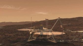
Several instruments are mounted on the Lander: the robotic arm (RA), the robotic arm camera (RAC), the thermal and evolved gas analyzer (TEGA), the Mars descent imager (MARDI), the meteorological station (MET), the surface stereo imager (SSI), and the microscopy, electrochemistry, and conductivity analyzer (MECA).


The RA was built by the Jet Propulsion Laboratory and was designed to perform the scouting operations on Mars, such as digging trenches and scooping the soil and water ice samples. RA delivered the samples to the TEGA and the MECA. RA is 2.35 meters long, it has an elbow joint in the middle, and it is capable of digging trenches 0.5 meters deep in the Martian soil.


The University of Arizona and the Max Planck Institute in Germany built the RAC. The camera is attached to the RA, just above the scoop placed at the end of the arm. RAC provided close-up, full-color images.


Credits: NASA / JPL


TEGA was developed by the University of Arizona and University of Texas, Dallas. TEGA used eight tiny ovens to analyze eight unique ice and soil samples. By employing a process called scanning calorimetry, and by using a mass spectrometer to analyze the gas obtained in the furnaces as the temperature raised to 1000 degrees Celsius, TEGA determined the ratio of various isotopes of hydrogen, oxygen, carbon, and nitrogen.


MARDI was built by Malin Space Science Systems. From what I could gather, the MARDI was not used by the Lander due to some integration issues.


The Canadian Space Agency (YAY Canada!) was responsible for the overall development of the meteorological station (MET). Two companies from Ontario, MD Robotics and Optech Inc., provided the instruments for the station.


The SSI served as the eyes of the Phoenix mission. SSI provided high-resolution, stereo, panoramic images of the Martian arctic. An extended mast holds the SSI, so the images were recorded from two meters above the ground.


Credits: NASA / JPL


MECA was built by the Jet Propulsion Laboratory. The instrument was used to characterize the soil by dissolving small amounts of soil in water. MECA determined the pH, the mineral composition, as well as the concentration of dissolved oxygen and carbon dioxide in the soil samples that were collected.


We would like to highlight some of the important moments during the mission:


August 4, 2007 – Delta II rocket launch from Cape Canaveral. The three-stage Delta II rocket with nine solid rocket boosters lifted off from Cape Canaveral, carrying the Phoenix spacecraft on the first leg of its journey to Mars.


Credits: NASA / JPL -Caltech / University of Arizona


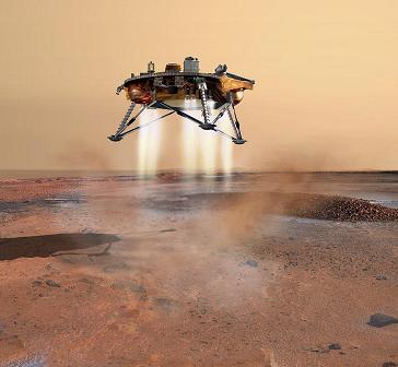
May 25, 2008 – Phoenix Mars Lander touchdown. The Phoenix entered the Martian atmosphere at 13,000 mph. It took 7 minutes for the Lander to slow down with the aid of a parachute and to land using its retrorockets. The mission team did not have to wait long before discovering ice because the blasts from the retrorockets had blown away the topsoil during landing and revealed ice patches under the lander.


November 2, 2008 – Last signal received from the Lander. On this date, communication was established for the last time with Phoenix. Due to the latitude of the landing site, not enough sunlight is available and the solar arrays are unable to collect the power necessary to charge the batteries that operate the instruments mounted on the Lander. At the landing site, the weather conditions are worsening.


November 10, 2008 – Mission declared completed. NASA declares that the Mars Phoenix Lander has completed a successful mission on the Red Planet. Phoenix Mars Lander has ceased communications after being operational for more than five months (the designed operational life of the mission was 90 days).


November 13, 2008 – Mission Honored. NASA’s Phoenix Mars Lander was awarded Best of What’s New Grand Award in the aviation and space category by Popular Science magazine.


Credits: NASA / JPL


The Mars Phoenix Lander made significant contributions to the study of the Red Planet. Phoenix verified the presence of water ice under the Martian surface, and it returned thousands of pictures from Mars. Phoenix also found small concentrations of salts that could be nutrients for life, it discovered perchlorate salt, and calcium carbonate, which is a marker of effects of liquid water.


Phoenix provided a mission long weather record, with data on temperature, pressure, humidity, and wind, as well as observations on snow, haze, clouds, frost, and whirlwinds.


Principal Investigator Peter H. Smith of the University of Arizona led the Phoenix mission. The project management was done at NASA’s Jet Propulsion Laboratory and the development at Lockheed Martin Space Systems in Denver. Other contributors were the Canadian Space Agency, the University of Neuchatel (Switzerland), the University of Copenhagen (Denmark), the Max Planck Institute (Germany), and the Finnish Meteorological Institute.


For more information about the Phoenix mission, check out the NASA Phoenix Mars Lander Page.


  • Facebook
  • Google
  • Slashdot
  • Reddit
  • Live
  • TwitThis