OrbitalHub

The place where space exploration, science, and engineering meet

Domain is for sale. $50,000,000.00 USD. Direct any inquiries to contact@orbitalhub.com.

Archive for the Microsatellites category


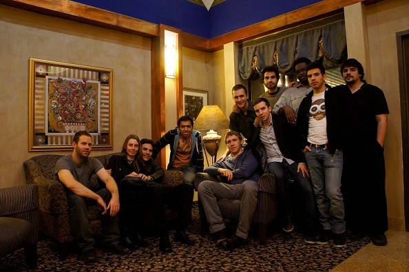
Credits: Space Concordia Team


The Canadian Satellite Design Competition (CSDC) is a Canada-wide competition for teams of university students (undergraduate and graduate) to design and build low-cost satellite. The CSDC plans to subject the satellites in competition to full space qualification testing, and to launch the winning satellite into orbit to conduct science research. The CSDC is modeled after existing university engineering competitions, such as those sponsored by the National Aeronautics and Space Administration (NASA) or the Society for Automotive Engineers (SAE).


The winning teammates are members of Space Concordia, a student-run astronautical engineering association based in the Faculty of Engineering and Computer Science at the Concordia University in Montreal. The selection process was conducted by industry experts at the David Florida Laboratory of the Canadian Space Agency in Ottawa, a highly secured facility where commercial and research satellites from the United States and Europe are routinely tested. From twelve teams that initially entered the competition, Space Concordia Team was among only three to go for final testing. Alex Potapov, Mechanical Team Lead, answered a few questions about the Space Concordia cubesat mission.


Q: What is the scientific payload for the mission you are designing?
A: Our mission is to study the south Atlantic anomaly, more on that here. We plan on doing this by detecting high energy particles present in the region. Our spacecraft is equipped with a Geiger Counter operating in its proportional mode. This will allow us to determine not only the amount of radiation but also the type of particle present.


Q: What hardware do you intend to use? Off-the-shelf boards and software or are you developing your own?
A: Most of our components are of the shelf with the exception of several printed circuit boards. One of the more impressive and less accessible pieces of hardware is the Xiphos Q6, which is a sophisticated FPGA that will be used as the central computer of our satellite. The software is developed internally, and it is based on the Linux operating system.


Q: How do you intend to communicate with your satellite from the ground? UHF, Iridium modem, etc.?
A: The spacecraft will communicate with a ground station located near Montreal by means of an antenna that is capable of transmitting and receiving at UHF and VHF armature frequency bands. At this orbit we will have a communication window of about 10-11 min per pass. The communication system was entirely developed by Tiago Leao, PhD Candidate at Concordia University.


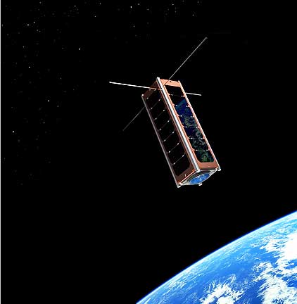
Credit: Space Concordia Team


Q: How do you generate and store power onboard the satellite? Batteries, solar panels? Do you intend to use deployable solar panels?
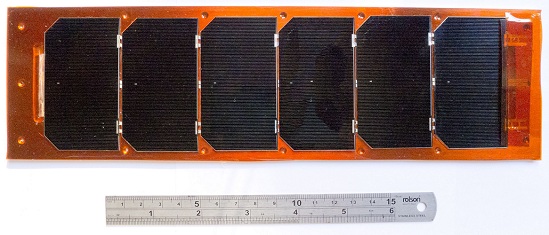
A: The satellite is equipped with four solar arrays made of 6 ultra high efficiency solar cells each, these cells charge 4 lithium ion batteries. The solar cells are mounted to the body panels of the spacecraft and are not deployable. The entire power system was designed and developed by Ty Boer, an electrical engineering student at Concordia University.


Q: Does the attitude determination and control system rely solely on reaction wheels? How do you intend to unload them? Magnetorquers, cold gas thrusters, or have you developed a novel technique?
A: Our approach to ACS does not require any of the above, the philosophy behind the cubesat was to keep it as simple as possible and still perform its mission, therefore a passive ACS system was selected. The system contains of permanent magnets and hysteresis rods, this will allow us to remain stable through communication window. We also have sun sensors for telemetry data.


Q: Do you plan to have any orbit control systems onboard? What is the orbital profile of the mission?
A: No, there is no active orbit control on-board. The flight software has a look up table that it uses to determine the spacecraft position, this table is updated through TLE data. We then use this position to execute certain commands such as power on the transmitter to establish communication.


Credit: Space Concordia Team / Concordia University


Q: How do you plan to control the temperature onboard the satellite?
A: The satellite has a passive cooling system, and active heaters that keep critical components such as the batteries within operating range. Cooling is controlled by careful design of conductive elements and optical surfaces.


Q: Who are the members registered with your team? What areas of expertise do they represent?
A: The Space Concordia core team members are: Nick Sweet (Project Manager), Alex Potapov (Mechanical team lead), Tiago Leao (Communication systems lead), Ty Boer (Power system lead), Shawn Stoute (Command and data handling lead), Alex Teodor (Software system lead), Gregory Gibson (ACS and Payload lead), Ivan Ivanov (Manufacturing Lead and Mechanical Design), Mehdi Sabzalian (Procurement lead, Structural analysis, Administration), Robert Jakubowicz (Senior Software Developer), Stefanos Dermenakis (Mechanical design, Thermal analysis), Andrei Jones (Mechanical Harness Design). You can find more about the contributors to the project on our about page.


To find out more about the Space Concordia Team, you can visit the Space Concordia web page. More information about the Canadian Satellite Design Competition can be found on the CSDC web page.


  • Facebook
  • Google
  • Slashdot
  • Reddit
  • Live
  • TwitThis
April 3, 2012

Dalhousie University T-Sat Project

Posted by


Credits: Clyde Space


The second Canadian Satellite Design Competition (CSDC) team that answered our invitation to a Q&A is the team from Dalhousie University. Colin O’Flynn, graduate student at Dalhousie University and CTO of the CSDC team, answered our questions.


Q: What hardware do you intend to use? Off-the-shelf boards and software or are you developing your own?
A: We are aiming to use COTS boards and software as much as possible, especially during development. Eventually we will be forced to design and build custom hardware, since there is a very specific form-factor which many COTS boards won’t fit inside. Weight is also a huge issue for us – since many COTS boards contain lots of features we might not need (e.g.: LCD display, Ethernet connector), we can shave some weight by spinning our own board and not wasting space or weight with those features.

Ideally though we’ll just adapt the COTS board design to our satellite, meaning we can use a tested design with minimal work. Not Invented Here (NIH) syndrome is dangerous to engineering projects, so while our current research does show we can’t find the correct form factor, we’ll always be checking the market for new products that might let us avoid needless designs and builds.


Q: How do you intend to communicate with your satellite from the ground? UHF, Iridium modem, etc.?
A: Again our satellite has slightly different objectives from a normal commercial satellite, which are primarily concerned with issues such as maximizing bandwidth or minimizing lag, since that gives the best return on investments.

In our project we also want to provide something with a wide scientific and public appeal. To that end we plan on using amateur radio frequencies – this means people around the world can track our satellite. Often amateur radio operators are on the lookout for interesting projects which introduce young students to radio communications. Letting students receiver data from a real satellite overhead does a lot to promote both amateur radio and space, which just maybe will help inspire the next generation of engineers.

Whether this will be in the S-Band or just UHF hasn’t been finalized yet, although there is potential to actually have a beacon running in the more common UHF, and our more bandwidth-intensive comms (e.g.: for downloading payload data) in S-Band. The actual coding technique will use more recent codes (e.g.: turbo or LDPC). Again since this is supposed to be a more ‘innovative’ approach to space, we are working with some of the respected professors and students in our department to get recent advances in both coding and antenna design on our spacecraft.


Q: How do you generate and store power onboard the satellite? Batteries, solar panels? Do you intend to use deployable solar panels?
A: The solar panels will not be deployable, but fixed on the outside surface, with batteries storing the charge. This area will use more mature technology. The power system is so critical, and since testing the components such as panels or batteries for the required environmental conditions is beyond our capabilities, we don’t want to rely on experimental designs.


Q: Does the attitude determination and control system rely solely on reaction wheels? How do you intend to unload them? Magnetorquers, cold gas thrusters, or have you developed a novel technique?
A: The satellite is very small; many Cubesats only use magnetorquers without reaction wheels. This limits what and where you can correct obviously, so we are still exploring more interesting techniques. We have “penciled in” reaction wheels and magnetorquers, but this could drastically change.

The attitude determination is also planned to be pretty standard. Due to the small size of sensors on the market, we actually plan on outfitting our satellite with a wide range of sensors beyond what is required for attitude determination. We plan on adding a three-axis magnetometer, gyro, and accelerometer, along with GPS receiver. The idea is to provide enough data for postprocessing on Earth for testing new algorithms, experiments, etc.


Q: Do you plan to have any orbit control systems onboard? What is the orbital profile of the mission?
A: Nothing planned yet; the orbit we are given is defined as:

The design orbit for the mission has the following parameters (TBC):

• Semi-major Axis: 7078 ± 100 km (600km to 800km altitude)

• Eccentricity: < 0.01
• Inclination: sun-synchronous for the resulting altitude

Launch details won’t be confirmed for some time, so some of this is mostly chance depending what we end up riding along with.

The only possible orbit control system we are investigating would be for deorbiting the satellite at the end of its life. Space is a shared resource, and we want to make sure we aren’t needlessly polluting it with our satellite. If it naturally will deorbit in a reasonable time this won’t be necessary, but it’s something we want to be sure of.


Credit: Dalhousie CSDC Team


Q: How do you plan to control the temperature onboard the satellite?
A: Currently something we are investigating. Preliminary calculations show we can do this passively to keep things within acceptable limits. Other Cubesats have done this in practice too.

We are trying to use automotive grade parts when possible, which gives us a better temperature range to work with. Understandably this isn’t possible for everything; the solar cells and battery are one obvious example.


Q: Who are the members registered with your team? What areas of expertise do they represent?
A: It’s a huge range of skills we have, including over a quarter that aren’t engineers or scientists. Our team is pushing outreach in the community, so for example running programs to introduce kids to space exploration, and the idea that it’s something they could become involved in themselves. Other sections of the team such as marketing, management, and finances are critical to our success, but have nothing to do with the core technical designs.

The technical team has about ten core members. The number of people working on the project though will be higher: we are defining senior year projects, which students will be able to get credit hours for. Time is always a problem in student run projects, so we are trying to make sure people get credit for all this work. Or as I like to point out: once they agree to help, they have to help, because otherwise they will fail the senior year project! It’s one way of retaining “volunteers”.


  • Facebook
  • Google
  • Slashdot
  • Reddit
  • Live
  • TwitThis
March 23, 2012

University of Manitoba T-Sat Project

Posted by


Credits: UMSATS Team


The Canadian Satellite Design Competition (CSDC) is a Canada-wide competition for teams of university students (undergraduate and graduate) to design and build low-cost satellite. The CSDC plans to subject the satellites in competition to full space qualification testing, and to launch the winning satellite into orbit to conduct science research. The CSDC is modeled after existing university engineering competitions, such as those sponsored by the National Aeronautics and Space Administration (NASA) or the Society for Automotive Engineers (SAE).


CSDC has other declared objectives as well:

• to promote education, excellence, research, development, and future capability in space activities in Canada.

• to foster innovation in satellite technologies and inexpensive access to space.

• to seek new applications of technologies and space missions for the betterment of Earth.


One of the teams in competition is the University of Manitoba Team, UMSATS. Dario Schor, UMSATS Project Lead, answered a few questions about the T-Sat (triple pico-satellite) designed by the University of Manitoba Team.


Q: What is the scientific payload for the mission you are designing?
A: The University of Manitoba mission carries two scientific payloads: a Tardigrade Experiment and a Solar Spectroscopy Experiment.

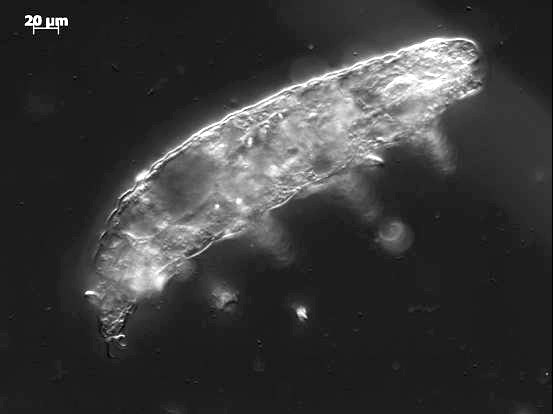
The Tardigrade Experiment aims to test the survivability of Tardigrades (a class of extremophile organisms also known as water bears) in space. This will be accomplished by sending a colony of tardigrades in a cryptobiosis state, exposing them to the harsh space environment, reviving them in orbit, and monitoring their behavior by taking bursts of images at predetermined times throughout the first 30-40 days of the mission. The novelty of the experiment is in the on-board revival of the organisms that has not been done in any satellite, let alone a nanosatellite that is only 10x10x30cm.

The Solar Spectroscopy Experiment measures the intensity of light emitted from the Sun over the ultraviolet to near-infrared regime (350nm to 1100 nm) to add and compare the results to theoretical models and data collected by other missions. This type of experiment has been performed on a number of missions with larger spacecrafts, thus demonstrating comparable results on a smaller and cheaper platform can open the door for many other small research groups to conduct similar experiments to collect and analyze their own data.


Credit: Scott McKay and Ravindi Gunasekara


Q: What hardware do you intend to use? Off-the-shelf boards and software or are you developing your own?
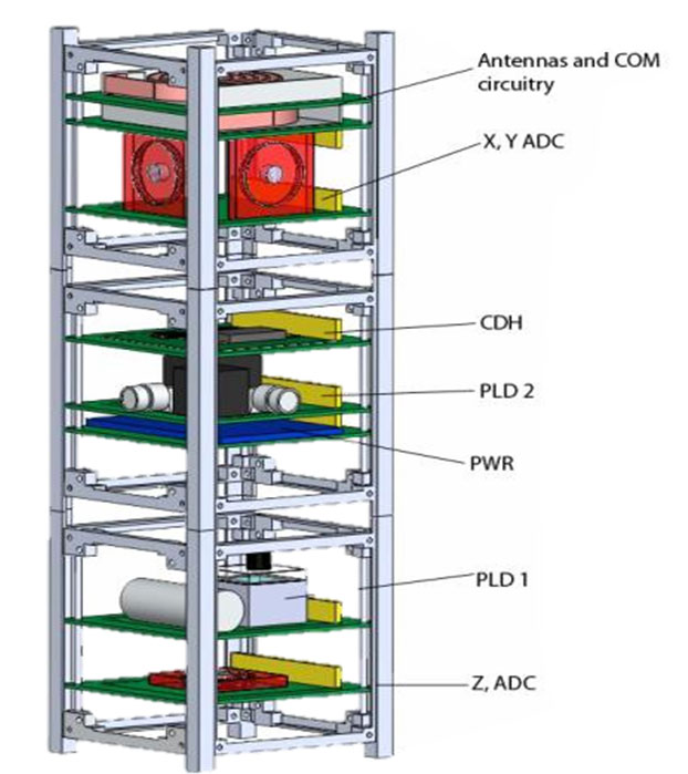
A: The spacecraft uses off-the-shelf components in custom designs for all subsystem boards. The extra efforts and risks from custom designs, manufacturing, and testing are offset by the experience gained by the students on the team. Some examples of the components used include:

• The Command & Data Handling (CDH) subsystem uses the TI MSP430 microprocessor interfaces to a watchdog timer, real-time clock, and memory modules for their operations.

• The Communications (COM) subsystem uses stripped down version of a commercial-off-the-shelf handheld from Yaesu that operates on amateur frequencies. Digital packets are created and encoded using a custom Terminal Node Controller based on the TI MSP430 microprocessor.

• The Power (PWR) subsystem uses fixed solar panels, an off-the-shelf battery, and a custom protection and distribution system to provide power to the spacecraft.

• The Structure (STR) is being built in-house out of Aluminum 6061. The custom design was required to support the two payload’s requirements for heat, volume, and position within the spacecraft.

• The Thermal (THM) subsystem relies primarily on insulation for its components and uses an off-the-shelf heater to maintain the Tardigrade experiment from freezing.

• The Attitude Determination and Control (ADC) subsystem uses off-the-shelf sensors, such as the Honeywell HMC2003 magnetometer, with customized designs for magnetic torque rods to control the orientation of the spacecraft.


Credit: UMSATS Team


Q: How do you intend to communicate with your satellite from the ground? UHF, Iridium modem, etc.?
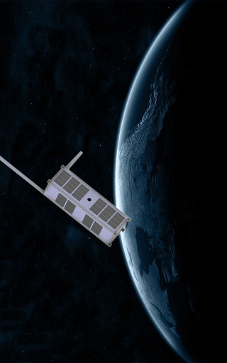
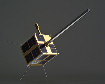
A: The spacecraft is designed to communicate with amateur radio stations conforming to the GENSO standard (genso.org). That means using the 2m band (144-148MHz) for uplink commands, and the 70cm (435-438MHz) for downlink telemetry and science, similar to many AMSAT satellites such as AO-51, HO-68, and FO-29. The spacecraft configurations with the two antennas is shown in Fig. 3. All packets are encoded using the AX.25 protocol that is compatible with most amateur ground stations, such as the University of Manitoba Satellite Ground Station.


Credit: UMSATS Team


Q: How do you generate and store power onboard the satellite? Batteries, solar panels? Do you intend to use deployable solar panels?
A: The spacecraft is designed to operate with a minimum of 4 Watts. Power is generated using fixed solar panels on all faces of the spacecraft and storing it in an on-board battery to power the spacecraft during eclipses. The fixed panels provide sufficient power for the mission without the added risks from deployable panels.


Q: Does the attitude determination and control system rely solely on reaction wheels? How do you intend to unload them? Magnetorquers, cold gas thrusters, or have you developed a novel technique?
A: The Attitude Determination and Control (ADC) subsystem uses a magnetometer and Sun sensors to determine the orientation of the spacecraft. Custom built magnetic torquers are used to control the orientation. The torquers are implemented in multilayered flat coils enabling easy integration of the torque rods with the rest of the system.


Q: Do you plan to have any orbit control systems onboard? What is the orbital profile of the mission?
A: There is no orbit control system onboard. This would be very difficult to achieve in a small 10x10x30 cm spacecraft with a maximum mass of 4kg as thrusters and fuel would require a large portion of the mass and volume leaving little room for scientific payloads.

The current goal is for a sun-synchronous orbit with an inclination of 98 degrees, eccentricity ~0, and altitude of approx. 600-800km. A sample profile for a 24 hr period for the mission is shown in Fig. 4. The field of view from the University of Manitoba Satellite Ground Station (operational since 2008) shows the contact points over the 24 hr period.


Credit: UMSATS Team


Q: How do you plan to control the temperature onboard the satellite?
A: The thermal control is mostly passive except for a heater attached to the Tardigrade payload to ensure the water and nutrients for the water bears do not freeze. Analysis of the temperature profiles revealed that the remaining components can stay within their allowed operating temperatures using small layers of insulation.


Q: Who are the members registered with your team? What areas of expertise do they represent?
A: The University of Manitoba team has over 100 registered students from Engineering, Science, Business, Architecture, Art, and Graduate Studies that contributed to the project since October 2010 with the largest group coming from the Department of Electrical and Computer Engineering. This includes students from first year all the way through Ph.D. programs, thus providing a strong core for this mission as well as laying the foundation for future missions at the University of Manitoba. At the moment, there is a core group of 35 students that are working on various aspects of the project.

The students are supported by a team of over 50 advisors from academia, industry (specifically aerospace from Magellan Bristol Aerospace), government, military, amateur radio community, and others. The advisors attend regular review meetings for the full project and some of the subsystems to provide feedback on the design.


To find out more about the UMSATS, you can visit the UMSTAS web page, or contact Dario Schor. More information about the Canadian Satellite Design Competition can be found on the CSDC web page.


  • Facebook
  • Google
  • Slashdot
  • Reddit
  • Live
  • TwitThis
October 3, 2011

Micro, nano, pico, and Sprite…

Posted by


Credits: NASA


Dr. Mason Peck, head of the Space Systems Design Studio at Cornell University, answered a few questions for OrbitalHub readers about the Sprite spacecraft. Peck earned a B.S. in Aerospace Engineering from the University of Texas at Austin, and his M.S. and Ph.D. at UCLA as a Howard Hughes Fellow.


A team at the Space Systems Design Studio focuses on Sprite, a simple, feasible design of spacecraft systems printed on small wafers of silicon. This design packages traditional spacecraft systems onto a single silicon microchip.


DJ: Miniaturization brings along quite a few limitations: small payloads and data storage, and much less power available. Why pursue miniaturization when designing a spacecraft?
Mason Peck: In fact, I would disagree with the word–and the concept of–miniaturization. It implies that the goal is to shrink an existing space-system architecture or technology here. Instead, the goals are the following:

– Start from the bottom and work up, i.e. from the level of fundamental technologies, and find out how little it might take to create a space system. If we start by focusing on a mission and consider the problem from the top down, or if we merely try to implement an existing solution at a smaller scale, we miss out on lots of opportunities for innovation.

– Without prejudice, ask how we explore at this small scale? Specifically, how does a very tiny spacecraft exploit the physics of the solar system to navigate, reorient, scavenge power, and the other housekeeping tasks that are fundamental to space exploration.

– And then, with this basic technology concept in place, ask what missions are possible? This approach is known sometimes as “technology push,” where the availability of some new function or performance motivates a new sort of exploration.

So, we expect to discover a kind of parallel universe of exploration possibilities, which has remained hidden from us because of our parochial view of what a spacecraft consists of. I’ll give you some examples in response to your third question.


DJ: How far can miniaturization go?
M.P.: One of our most surprising discoveries is that commercial, off-the-shelf electronics components for mainstream contemporary applications like cell phones and iPods are vastly superior in performance to typical spacecraft electronics. Most people understand that spacecraft electronics are several generations behind the state of the art, and for good reasons such as needing radiation-hard parts, flight-proven reliability, etc. But what’s astonishing is just how far ahead consumer electronics are. We’ll be able to implement GPS-based orbit knowledge, radio communications, and attitude sensing all on about 1 cm^2 of integrated circuitry, using catalog components that anyone can buy. And they’re remarkably cheap, mostly because they’re made in the millions: single-chip GPS receivers, little CMOS cameras, etc. are no more than a few $ each in some cases.

The reliability or survivability of these off-the-shelf components is certain to be much poorer than flight-qualified parts. However, remember that at this scale of size and cost, fabricating and launching thousands or millions is entirely within reach. A single ChipSat may be unreliable, but the cloud of them may offer very high reliability. More than that, a cloud can be understood statistically, with notions like “statistical confidence,” which are very hard to come by when one is building a single, exquisite spacecraft.

A ChipSat will never replace Hubble, but it would not be expected to do so. Instead, ChipSats would form the basis of exploration missions that benefit from a large number of distributed, although coarse, measurements. More generally, this notion of “technology push” introduces a transformative idea for scientists. Instead of posing a science mission that presupposes a spacecraft architecture, let innovation in mission-science objectives couple with engineering innovation. That’s how we’ll do new, remarkable things.


DJ: Can you give some examples of mission scenarios envisioned for swarms of Sprite spacecraft?
M.P.: One of my favorites is that a Sprite may be able to enter a planetary atmosphere without parachutes, rockets, or a heat shield, and yet never burn up. Some of our early work on this problem for Earth’s atmosphere suggests that a 25 micron thick Sprite can reenter without burning up and maintain a cool enough temperature that electronics can continue to operate. So, reentering Sprites can sample the ionosphere, the mesosphere, and on down to the surface of the Earth. We’d get unprecedented measurements of spatial and temporal phenomena like turbulence and particle densities.

Another idea is to place a cloud of these Sprites between the Earth and the Sun, maybe at a so-called Lagrange point, which would be a sort of orbital equilibrium between the two. Each Sprite in the cloud would have the simple task of transmitting a single bit when solar-wind flux or magnetic flux exceeded some threshold, indicating a solar storm. This data would offer a distributed measurement for science, but at least as important it would provide a new type of advance warning of these storms, which can knock out radio communications on Earth.

Yet another application is a bit of science fiction, but it gets us thinking along new lines. Consider a particle accelerator. On Earth, these systems accelerate charged particles like electrons to relativistic velocities so that physicists can study subatomic phenomena. Now imagine the Sprite as a particle. It would be electrostatically charged, like a toy balloon on a dry day, and in that way resembles a very large electron. Could we build a kind of particle accelerator to launch Sprites out of the solar system at very high speed? The Navy already has a railgun that uses electromagnetic effects to launch large masses. Their recent successes show that the concept is perfectly sound. In fact, if you could direct the energy of their 30 kg railgun into a, say, 30 mg Sprite, that’s a factor of 1000 higher speed. Such a Sprite could be the first interstellar explorer. Michio Kaku and I have discussed the wild notion of a ring-shaped Sprite accelerator on the moon or in Jupiter’s orbit (in fact, the idea appeared on his Sci Fi Science TV show). In principle, such a launch system could send a Sprite to the nearest star system in a few decades.


DJ: The small mass and size of a Sprite spacecraft does not leave much room for radiation shielding. Especially during deep space missions, single events can take a spacecraft out of commission. How can Sprite spacecraft compensate for these inherent hazards of space travel?
M.P.: Absolutely right. Radiation will degrade the Sprite until it stops functioning. The easiest solution is simply to produce a rad-hardened chip. They’re not uncommon, although it’s expensive to design and build them. But it can be done, and amortizing that cost over millions of Sprites would make doing so a lot more appealing than how it’s done now, where we go to all that effort for a relatively small number of chips. But if you don’t want to get into rad hardening, remember that this effect is a statistical one. So, using a large enough number of Sprites for a mission would be a way to ensure that a desired fraction of them survive, even though a large number would fail. Again, we could design in this statistical reliability. And the more you use, the more reliably the mission meets its objectives.


DJ: Sprite is by definition a propellantless spacecraft. What type of propulsion can be employed?
M.P.: I wouldn’t be against trying to implement traditional propulsion at this scale. In fact, it’s been done, with mixed success. But the reason to pursue propellantless technologies is that chemical propulsion does not scale down well.

We find that several approaches do scale well. First, solar sailing is a clear winner. With a thin but still rigid silicon wafer, we can get performance benefits similar to the vast solar sails that have been proposed, but with the important advantage that the sail is not a floppy mess, difficult to deploy and steer around. The acceleration of a solar-sail Sprite increases with 1/L, where L is the length scale. As long as there are no limitations on thickness, a uniformly shrunken solar sail works better than its larger analogue. For example, a 1m solar sail accelerates 10x as fast as a 10m solar sail, as long as the thickness scales proportionately. That proportionate scaling may be tough to achieve, but what’s easy is the stiffness: a 25 micron Sprite is stiff enough that it needs no deployable booms or trusses, and it’s therefore effectively thinner (less mass for the area) than the larger sails.

A little harder to implement but even more intriguing is electrodynamic tether technology. Sprite sends a current through a wire that extends from the spacecraft, grounded in the ionospheric plasma. The current interacts with the Earth’s magnetic field, like the windings in an electric motor, producing a force. That force can accelerate the spacecraft. Just like the solar-sailing example, an ED tether is a lot more convenient when it’s shorter: it’s basically a rod, not a floppy string. The dynamics-related problems that the Space Shuttle tether experiments encountered would not arise here.


DJ: How many Sprite spacecraft are currently deployed and what kind of payloads do they have?
M.P.: There are three prototypes on the outside of the International Space Station. They’re not free-flying. They’re self-powered with solar cells, and they have their own on-board computers, radios, and other circuitry. They are their own payload in the sense that if they communicate, we’ll be able to confirm that Sprite’s unique communications architecture is a valid design. We didn’t have time (and we had no money, in fact) for a science payload per se.


DJ: Swarms of hundreds of decommissioned Sprite spacecraft orbiting the Earth could make mission flight control rooms very nervous. Are there any post-mission disposal methods considered for Sprite missions?
M.P.: Yes and no. Space debris is certainly a risk, but Sprites do not have to be debris. In low-earth orbit, their unique flight dynamics mean that aerodynamic drag very quickly pulls them back into the atmosphere. Specifically, a 325 km orbit would decay in about 2 days. Even at 500 km, they would reenter in weeks, at most. If they burn up, that’s that. If they don’t, it’s because they’re so delicate that they would never hurt anyone even if one were to land on a person on the ground. So, they clean up after themselves.


DJ: What are the areas with room for improvement in the design and manufacturing of chip-sized satellites?
M.P.: The next step will be that the design will transition from discrete parts to a single, application-specific integrated circuit (ASIC). That’s the real objective. It would be far lighter, less power-hungry, and more maneuverable than the current prototypes on ISS.


Credits: Zac Manchester


To find out more about the Sprite Spacecraft, Dr. Mason Peck, and his team at Cornell University, please visit the Space Systems Design Studio webpage. Paul Gilster of Centauri Dreams has also covered this topic in ’Smart Dust’ and Solar Sails and Tiny Spacecraft Point to Future Sails.


  • Facebook
  • Google
  • Slashdot
  • Reddit
  • Live
  • TwitThis
January 29, 2011

MSCI Announces Satellite Constellation

Posted by
Credits: MSCI


The COMMStellation satellites will orbit the Earth on polar orbits 1,000 km above the surface of the Earth. The satellites will be deployed in six orbital planes, thirteen operational satellites per plane, plus one for redundancy. The deployment will be cost efficient, only six launches being required to deploy the whole constellation.


As oppose to Iridium, which is accessible from portable devices, the COMMStellation will be connected to terrestrial telecommunication networks through twenty ground stations located around the Earth. The required ground stations are less expensive than those used for communication with satellites on medium Earth orbits and geostationary orbits.


MSCI claims it has perfected the construction of microsatellites and the use of commercial-grade components for development of microsatellites. These factors have led to low manufacturing costs and improved schedules.


An alternative to COMMStellation is proposed by O3b Networks, located in St. John, Jersey, Channel Islands. The O3b Networks constellation satellites will provide broadband connectivity within forty-five degrees latitude north and south of the equator. The constellation will consist of eight satellites at 8,000 km above the surface of the Earth. There are a number of advantages in using the low Earth orbit polar microsatellites, as MSCI is proposing, over using equatorial medium Earth orbit satellites: the polar orbits provide full coverage of the terrestrial surface and microsatellite technology has less cost and increased reliability associated with it.


It is also worth mentioning a previous attempt at creating a constellation of low Earth orbit satellites to provide access to the Internet – Teledesic.


You can read more about COMMStellation on MSCI’s website.


  • Facebook
  • Google
  • Slashdot
  • Reddit
  • Live
  • TwitThis
November 27, 2010

AISsat-1 Mission Needs Votes

Posted by


Credits: FFI


AIS, which stands for Automatic Identification System, provides navigation aid and works as an anti-collision system for vessels at sea. As of December 31, 2004, as required by IMO (the International Maritime Organization), an AIS device must be fitted aboard all passenger ships, all ships engaged on international voyages that have more than 300 gross tonnage, and cargo ships not engaged on international voyages that have more than 500 gross tonnage.


AIS devices aboard the ships broadcast messages containing position reports and short messages with information about the ship and the voyage. These messages are sent on two channels in the maritime VHF to neighboring vessels and to VTS (Vessel Traffic Services) stations on the shore. These messages can also be picked up by a VHF receiver in low Earth orbit (LEO). This is how the idea of space monitoring of AIS signals was born.


Norway, a nation having long shore lines and large fishing grounds in its coastal waters, pioneered this new concept. AISsat-1 is a nanosatellite technology demonstration mission in LEO, funded by the NSC (the Norwegian Space Center). The technical implementation is the responsibility of the FFI (Norwegian Defense Research Establishment).


AISsat-1 is a cube-shaped nanosatellite measuring 20 x 20 x 20 cm that weighs six kilograms. AISsat-1 has been built at UTIAS (the University of Toronto Institute for Aerospace Studies). The payload on AISsat-1, the AIS sensor, was developed by Kongsberg Seatex AS (KSX) of Trondheim, Norway.


The satellite design is based on the Generic Nanosatellite Bus (GNB) developed at UTIAS. GNB contains all the necessary components for a typical satellite mission: a TT&C and payload data communication system, a 3-axis attitude determination and control system, and a dual-battery, gallium-arsenide triple-junction solar cell based power system. GNB has a large accommodation for scientific payloads in terms of volume, power, computing power, and spacecraft surface area.


AISsat-1 shared a ride to space on a multi-payload mission on the PSLV-C15 launch vehicle on July 12, 2010. PSLV lifted off from Satish Dhawan Space Centre (SDSC), Sriharikota, India. The satellite has been placed into a polar orbit at 98.1 degrees inclination with perigee at 626 km and apogee at 642 km. The orbit has a period of 97.3 minutes.


The ground station that acquires data from AISsat-1 during the 15 daily passes over Norwegian waters is the Svalbard Ground Station, located on the Norwegian Svalbard archipelago, near the town of Longyearbyen. The ground station is storing data for subsequent forwarding to the mission control center located at FFI in southern Norway.


AISsat-1 has entered the Norwegian Top Technological Achievement Competition for 2010. You are invited to cast your vote for AISsat-1, a mission based on Canadian nanosatellite technology. You can submit your vote by the end of this Sunday, November 28, 2010, on this webpage. If you have difficulties understanding Norwegian, this Google Translate link will do the trick for you. Go Canada!


You can find more information about AISsat-1 on the Norwegian Space Centre’s website.


  • Facebook
  • Google
  • Slashdot
  • Reddit
  • Live
  • TwitThis